Cable television apparatus with high saturation current transformer

a transformer and high-saturation current technology, applied in the direction of transformer/inductance magnetic core, television system, coupling device connection, etc., can solve the problems of poor high-frequency characteristics and increase so as to improve the high-frequency characteristics of the cable television signal and reduce the cost of the cable television system.

Pending Publication Date: 2022-01-27
CABLE VISION ELECTRONICS
View PDF0 Cites 1 Cited by
  • Summary
  • Abstract
  • Description
  • Claims
  • Application Information

AI Technical Summary

Benefits of technology

[0026]Because the present invention does not use the choke to transmit the alternating current power, the present invention can greatly improve the high frequency characteristics of the cable television signal and reduce the cost of the cable television system.

Problems solved by technology

Usually, the choke needs the winding, wherein the length of the winding is long, so that the choke easily generates the parasitic capacitances and the parasitic inductances; the notch (the undesired resonance) is generated easily at the high frequency, so that the high frequency characteristics are not good, especially at the frequency band above 1.5 GHz.
Moreover, using the choke in the cable television system increases the cost of the cable television system as well.

Method used


Image

  • Cable television apparatus with high saturation current transformer
  • Cable television apparatus with high saturation current transformer
  • Cable television apparatus with high saturation current transformer

Examples


first embodiment

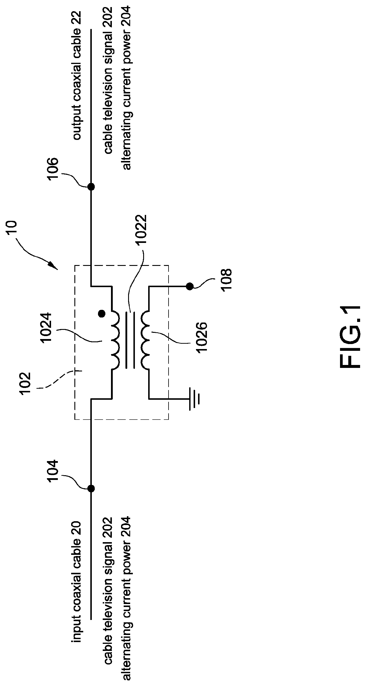
[0037]FIG. 1 shows a circuit block diagram of the cable television apparatus of the present invention. The cable television apparatus 10 of the present invention is applied to an input coaxial cable 20 and an output coaxial cable 22 to transmit a cable television signal 202 and an alternating current power 204. The cable television apparatus 10 comprises a high saturation current transformer 102, an input terminal 104, an output terminal 106 and a coupling side 108. The high saturation current transformer 102 comprises a ferrite core 1022, a primary side circuit 1024 and a secondary side coil 1026. The components mentioned above are electrically connected to each other, and the secondary side coil 1026 winds the ferrite core 1022 (as shown in FIG. 5).

[0038]The ferrite core 1022 is a high saturation current ferrite core, so that the primary side circuit 1024 transmits the cable television signal 202 and the alternating current power 204, and couples the cable television signal 202 to...

second embodiment

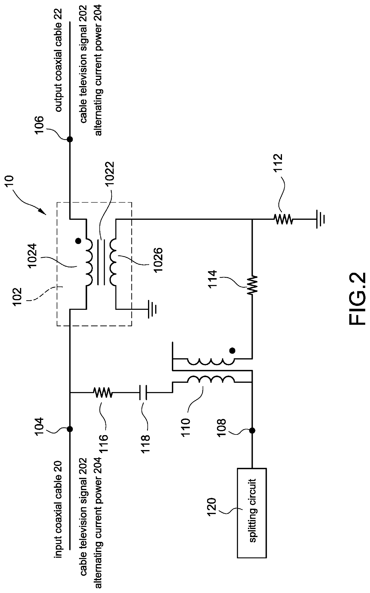
[0042]FIG. 2 shows a circuit block diagram of the cable television apparatus of the present invention. The descriptions of the elements shown in FIG. 2 which are the same as the elements shown in the figures mentioned above are not repeated here for brevity. The cable television apparatus 10 further comprises a coupling side transformer 110, a first resistor 112, a second resistor 114, a third resistor 116, a capacitor 118 and a splitting circuit 120. The components mentioned above are electrically connected to each other.

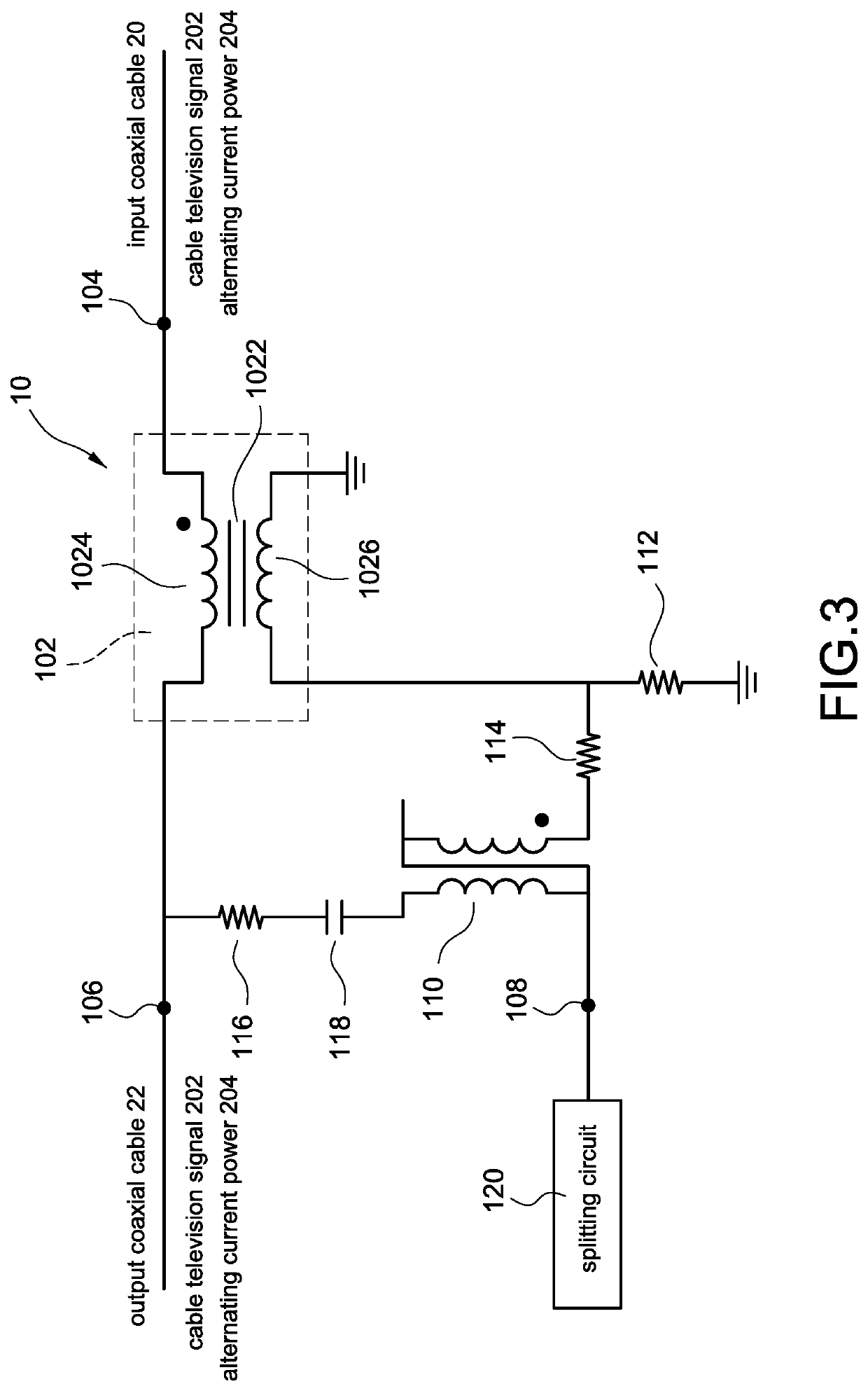
[0043]FIG. 3 shows a circuit block diagram of the third embodiment of the cable television apparatus of the present invention. The descriptions of the elements shown in FIG. 3 which are the same as the elements shown in the figures mentioned above are not repeated here for brevity. FIG. 4 shows a circuit block diagram of the fourth embodiment of the cable television apparatus of the present invention. The descriptions of the elements shown in FIG. 4 which are the s...


PUM

PropertyMeasurementUnit
bearable currentaaaaaaaaaa
diameteraaaaaaaaaa
frequencyaaaaaaaaaa

Abstract

A cable television apparatus is applied to an input coaxial cable and an output coaxial cable to transmit a cable television signal and an alternating current power. The cable television apparatus includes a high saturation current transformer, an input terminal, an output terminal and a coupling side. The high saturation current transformer includes a ferrite core, a primary side circuit and a secondary side coil. The ferrite core is a high saturation current ferrite core, so that the primary side circuit transmits the cable television signal and the alternating current power, and couples the cable television signal to the secondary side coil.

Description

BACKGROUND OF THE INVENTIONField of the Invention[0001]The present invention relates to a cable television apparatus, and especially relates to a cable television apparatus with a high saturation current transformer.Description of the Related Art[0002]Currently, the cable television system is very popular. The cable television system transmits the television programs and the network signals to the client sides through the coaxial cables.[0003]The cable television system needs to use the choke to transmit the alternating current power. Usually, the choke needs the winding, wherein the length of the winding is long, so that the choke easily generates the parasitic capacitances and the parasitic inductances; the notch (the undesired resonance) is generated easily at the high frequency, so that the high frequency characteristics are not good, especially at the frequency band above 1.5 GHz.[0004]Moreover, using the choke in the cable television system increases the cost of the cable tele...

Claims


Application Information

Patent Timeline
Patent Type & Authority Applications(United States)
IPC IPC(8): H04N7/10H01F27/24H01F27/28H03H7/06H01R24/42
CPCH04N7/104H01F27/24H01R2103/00H03H7/06H01R24/42H01F27/28H04N7/102H01F38/30H01F2038/305H01R13/6633H03H7/48
Inventor LEE, CHIEN-CHUNGYU, MAO-PENGTING, I-SHENG
Owner CABLE VISION ELECTRONICS
Why Eureka
Try Eureka