Common mode filter

a filter and mode filter technology, applied in the direction of inductances, inductances with magnetic cores, transformers/reacts mounting/support/suspension, etc., can solve the problems of inability to meet the needs of increasing the length the low so as to achieve a higher signal balance, improve the effect of signal balance and improve the utilization efficiency of the winding core par

Active Publication Date: 2019-01-29
TDK CORPARATION
View PDF11 Cites 1 Cited by
  • Summary
  • Abstract
  • Description
  • Claims
  • Application Information

AI Technical Summary

Benefits of technology

[0007]It is therefore an object of the present invention is to further improve the high-frequency characteristics of the common mode filter having the bifilar winding part and layer winding part.

Problems solved by technology

However, the bifilar winding is low in the utilization efficiency of a winding core part, so that the length of the winding core part inevitably needs to be increased to ensure necessary inductance.

Method used


Image

  • Common mode filter
  • Common mode filter
  • Common mode filter

Examples


first embodiment

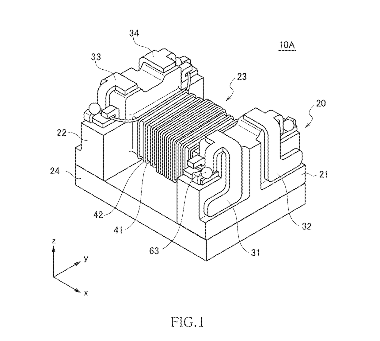
[0031]FIG. 1 is a schematic perspective view illustrating the outer appearance of a common mode filter 10A according to the first embodiment of the present invention.

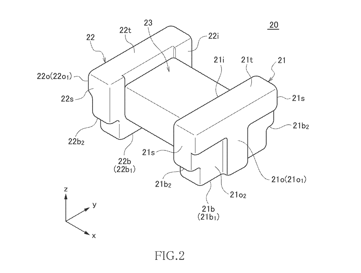
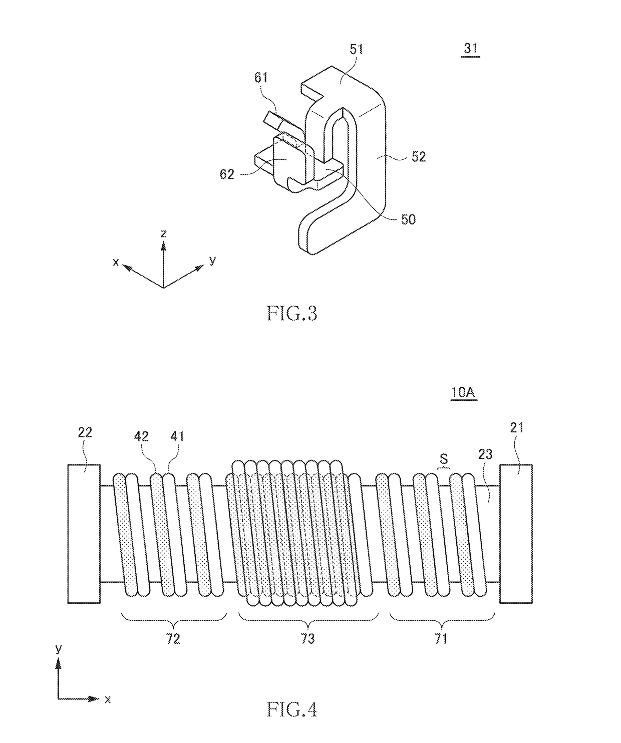
[0032]As illustrated in FIG. 1, the common mode filter 10A according to the present embodiment includes a drum core 20, a plate core 24, first to fourth terminal electrodes 31 to 34, and first and second wires 41 and 42. The structure of the core 20 is illustrated in FIG. 2, and the structure of the first terminal electrode 31 is illustrated in FIG. 3. The cores 20 and 24 are each formed of a magnetic material having a comparatively high permeability, such as an Ni—Zn based ferrite. The first to fourth terminal electrodes 31 to 34 are each a metal fitting formed of a good conductor material such as copper.

[0033]The core 20 has a first flange part 21, a second flange part 22, and a winding core part 23 disposed between the first and second flange parts 21 and 22. The winding core part 23 has its axis direction in the x-d...

second embodiment

[0049]FIG. 5 is a schematic view for explaining the winding layout in a common mode filter 10B according to the second embodiment of the present invention.

[0050]As illustrated in FIG. 5, the common mode filter 10B according to the present embodiment differs from the common mode filter 10A according to the first embodiment in the winding layout in the third winding region 73. Other basic configurations are the same as those of the common mode filter 10A according to the first embodiment, so the same reference numerals are given to the same elements, and overlapping description will be omitted.

[0051]In the present embodiment, the third winding region 73 includes first and second layer regions 81 and 82, and the first and second wires 41 and 42 cross each other at a cross point 83 positioned between the first and second layer regions 81 and 82. The first layer region 81 is positioned on the first winding region 71 side, where the first and second wires 41 and 42 are each wound in five ...

third embodiment

[0059]FIG. 11 is a schematic view for explaining the winding layout in a common mode filter 10C according to a third embodiment of the present invention.

[0060]As illustrated in FIG. 11, the common mode filter 10C according to the present embodiment differs from the common mode filter 10B according to the second embodiment in the winding layout in the third winding region 73. Other configurations are the same as those of the common mode filter 10B according to the second embodiment, so the same reference numerals are given to the same elements, and overlapping description will be omitted.

[0061]In the present embodiment, in both the first and second layer regions 81 and 82, the first wire 41 is wound in the lower layer, and the second wire 42 is wound on the first wire 41. However, as described above, in the layer winding, one turn of the wire to be wound in the upper layer is dropped to the lower layer. Thus, in the present embodiment, one turn of the second wire 42 is dropped to the...


PUM

PropertyMeasurementUnit
distanceaaaaaaaaaa
parasitic capacitanceaaaaaaaaaa
high-frequency characteristicsaaaaaaaaaa

Abstract

Disclosed herein is a common mode filter that includes first and second terminal electrodes provided on the first flange part, third and fourth terminal electrodes provided on the second flange part, a first wire wound around the winding core part and having one end connected to the first terminal electrode and other end connected to the third terminal electrode, and a second wire wound around the winding core part and having one end connected to the second terminal electrode and other end connected to the fourth terminal electrode. The winding core part includes a first winding region, a second winding region, and a third winding region positioned between the first and second winding regions in the axial direction. The first and second wires are bifilar-wound in the first and second winding regions and layer-wound in the third winding region.

Description

BACKGROUND OF THE INVENTIONField of the Invention[0001]The present invention relates to a common mode filter and, more particularly to a common mode filter excellent in high frequency characteristics.Description of Related Art[0002]A common mode filter is widely used in many electronic devices such as mobile electronic devices and on-vehicle LANs to remove common mode noise superimposed on differential signal lines. In recent years, a common mode filter using a surface-mountable drum core supersedes a common mode filter using a toroidal core (see Japanese Patent Application Laid-open No. 2008-208331).[0003]As a winding method of a wire around the drum core, a bifilar winding and a layer winding are known. The bifilar winding is a type of winding where two wires are wound in parallel in the same turn and has advantages in that it can obtain good signal balance and has less unnecessary parasitic capacitance. The layer winding is a type of winding where first and second wires are wound...

Claims


Application Information

Patent Timeline
Patent Type & Authority Patents(United States)
IPC IPC(8): H01F27/06H01F41/069H01F27/00H01F27/28H01F17/04H01F5/00H03H1/00H01F17/00
CPCH03H1/00H01F5/00H01F17/045H01F27/006H01F41/069H01F27/2823H03H2001/0092H01F2017/0093H03H2001/0021H03H2001/0035H03H7/427
Inventor KOBAYASHI, TSUTOMUTOMONARI, TOSHIOITO, EMIKOYAMA, YUMA
Owner TDK CORPARATION
Why Eureka
Try Eureka