Airbag device with exhaust hole

a technology of airbags and exhaust holes, which is applied in the direction of pedestrian/occupant safety arrangements, vehicular safety arrangments, vehicle components, etc., to achieve the effect of suppressing windshield damag

Active Publication Date: 2021-09-21
TOYODA GOSEI CO LTD
View PDF28 Cites 2 Cited by
  • Summary
  • Abstract
  • Description
  • Claims
  • Application Information

AI Technical Summary

Benefits of technology

[0006]An object of the invention is to provide an airbag device which can accurately protect an occupant by an inflated airbag with a simple configuration.
[0009]In the airbag device of the invention, the airbag is configured such that the dummy inflation portion is provided at a position approximately symmetrical to the discharge portion at the time of inflating completion, but the dummy inflation portion is configured to be inflated to partially protrude from the bag body by the inflation gas flowing to the inside at the time of deployment and inflation of the airbag, regardless of the behavior of the discharge portion (operation of the opening / closing control device). That is, in the airbag device of the invention, the dummy inflation portion is not connected to the opening / closing control device side, and only the connection member extending from the discharge portion is connected to the opening / closing control device. Therefore, it is possible to configure the device itself with a simple configuration as compared with an airbag device in the related art in which the dummy inflation portion is also connected to the opening / closing control device side. In the airbag device of the invention, since the dummy inflation portion is provided, in a case where the discharge portion is inflated to protrude outwardly from the bag body so as to open the exhaust hole by releasing the connection between the connection member and the opening / closing control device, the dummy inflation portion also partially protrudes to be disposed at a position approximately symmetrical to the discharge portion, and thus the bag body can be inflated symmetrically in a balanced manner. Further, in the airbag device of the invention, in a case where the discharge portion is inflated in a state of being drawn into the bag body by the connection between the connection member and the opening / closing control device being maintained, only the dummy inflation portion partially protrudes from the bag body, and the airbag is inflated in an asymmetric state. However, in the airbag device of the invention, since the volume of the dummy inflation portion at the time of inflating completion is set to be smaller than the volume of the discharge portion in a state where the exhaust hole is open at the time of inflation, the bag body can be stably inflated without greatly losing balance.
[0010]Accordingly, in the airbag device of the invention, it is possible to accurately protect an occupant by the inflated airbag with a simple configuration.
[0012]With the above-described configuration of the airbag device, in the airbag at the time of inflating completion, it is possible to suppress that parts becoming bulky (harden) by binding the peripheral edges of the base material are disposed to be concentrated in the vicinity of the center, in the right-left direction, of a region on the upper surface side provided on the windshield side. Therefore, even in a case where the upper surface side of the airbag at the time of inflating completion is provided to be close to the windshield, it is possible to suppress a damage on the windshield due to the inflated airbag.

Problems solved by technology

However, in the airbag device in the related art, since the dummy tube is also connected to the opening / closing control device side by a second connection member extending from the distal end side and the connection between the dummy tube and the opening / closing control device is configured to be maintained or released, the configuration is complex, and thus there is room for improvement in terms of simplifying the configuration.

Method used


Image

  • Airbag device with exhaust hole
  • Airbag device with exhaust hole
  • Airbag device with exhaust hole

Examples


Embodiment Construction

[0027]Preferred embodiments of the present invention are described below with reference to the accompanying drawings. However, the invention is not limited to the embodiments disclosed herein. All modifications within the appended claims and equivalents relative thereto are intended to be encompassed in the scope of the claims.

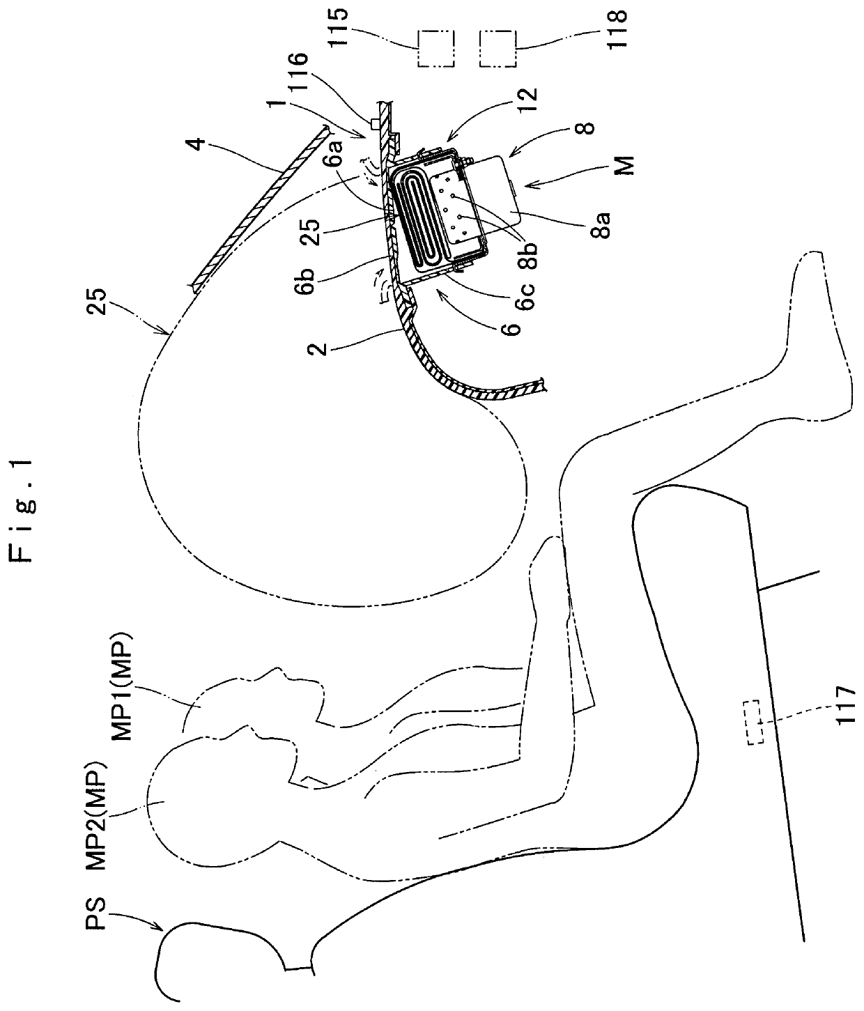
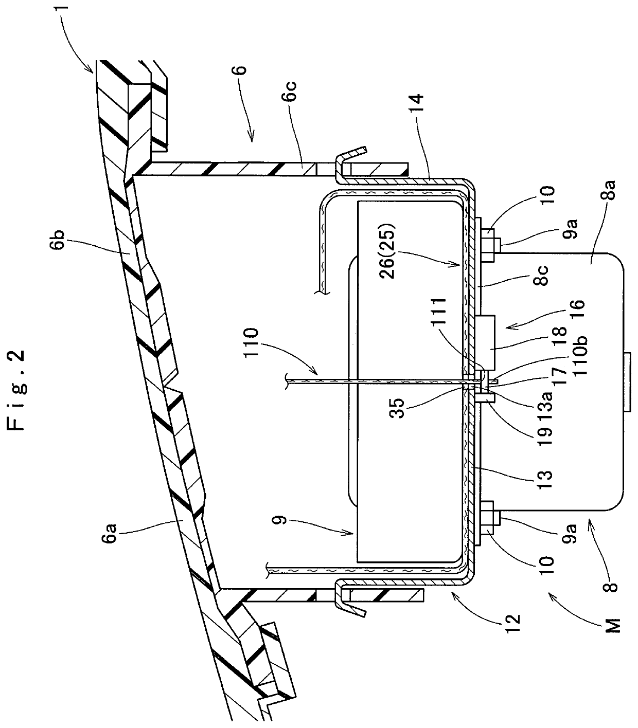
[0028]Hereinafter, an embodiment of the invention will be described based on the drawings. In the embodiment, description is made using a passenger seat airbag device M (hereinafter, abbreviated as an “airbag device”) which can protect an occupant MP sitting on a passenger seat PS, as an example. The airbag device M of the embodiment is a top mount type that is disposed in an upper surface 2 of an instrument panel 1 in front of the passenger seat PS in a vehicle, as illustrated in FIGS. 1 and 2. In the embodiment, a front-rear direction, an up-down direction, and a right-left direction are the same as a front-rear direction, an up-down direction, and a right-l...


PUM


Abstract

An airbag having an exhaust hole and an opening / closing control device configured to control opening and closing of the exhaust hole are provided. The airbag includes a bag body, and a discharge portion having the exhaust hole, the discharge portion is configured to maintain a blocked state of the exhaust hole by being drawn into the bag body at the time of inflation of the bag body in a state where connection between a connection member and the opening / closing control device is maintained, and to be inflated by protruding from the bag body at the time of inflation of the bag body in a state where the connection between the connection member and the opening / closing control device is released to open the exhaust hole. A dummy inflation portion inflated to partially protrude from the bag body is formed at a position approximately symmetrical to the discharge portion. A volume of the dummy inflation portion at the time of inflating completion is set to be smaller than a volume of the discharge portion in a state where the exhaust hole is open at the time of inflation.

Description

CROSS REFERENCE TO RELATED APPLICATIONS[0001]The Present application claims priority from Japanese Patent Application No. 2018-180841 of Hiraiwa et al., filed on Sep. 26, 2018, the entire disclosure of which is incorporated herein by reference.BACKGROUND OF THE INVENTIONField of the Invention[0002]The invention relates to an airbag device including an airbag which is folded and housed in a housing part and is configured to be inflated to protrude from the housing part by an inflation gas flowing to the inside of the airbag, and of which an internal pressure at the time of inflating completion is controllable.Background Art[0003]In the related art, as an airbag device, JP-2009-227047 discloses a configuration in which an exhaust hole through which some of the inflation gas is discharged is provided to a passenger seat airbag, opening and closing of the exhaust hole are controlled by an opening / closing control device in accordance with a physique and a sitting position of an occupant ...

Claims


Application Information

Patent Timeline
Patent Type & Authority Patents(United States)
IPC IPC(8): B60R21/239B60R21/233B60R21/2338
CPCB60R21/239B60R21/233B60R21/2338B60R2021/2395B60R2021/23382B60R2021/23384B60R2021/23308B60R2021/23538
Inventor HIRAIWA, TAKUYAISHIDA, SHINICHISUZUKI, KEITA
Owner TOYODA GOSEI CO LTD
Why Eureka
Try Eureka