
Backlight module and display apparatus

a backlight module and display device technology, applied in the field of viewing angle control technology, can solve problems such as leakage of confidential information, and achieve the effect of improving the convenience of operation of the display devi

Active Publication Date: 2021-10-19
CORETRONIC
View PDF6 Cites 2 Cited by
  • Summary
  • Abstract
  • Description
  • Claims
  • Application Information

AI Technical Summary

Benefits of technology

[0006]The invention provides a display apparatus exhibiting favorable anti-peep performance.
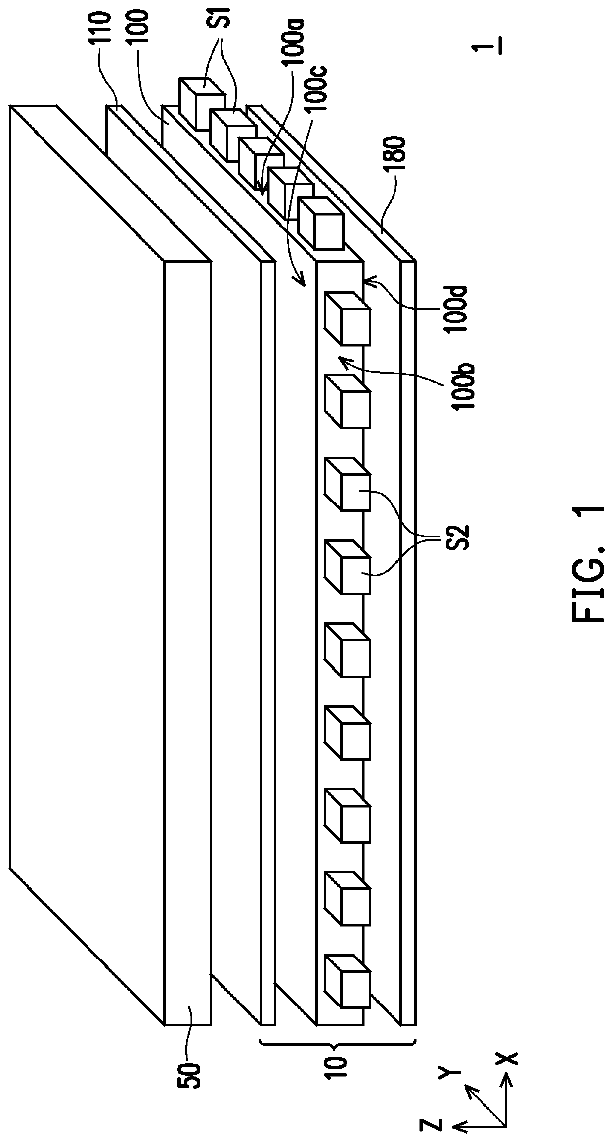
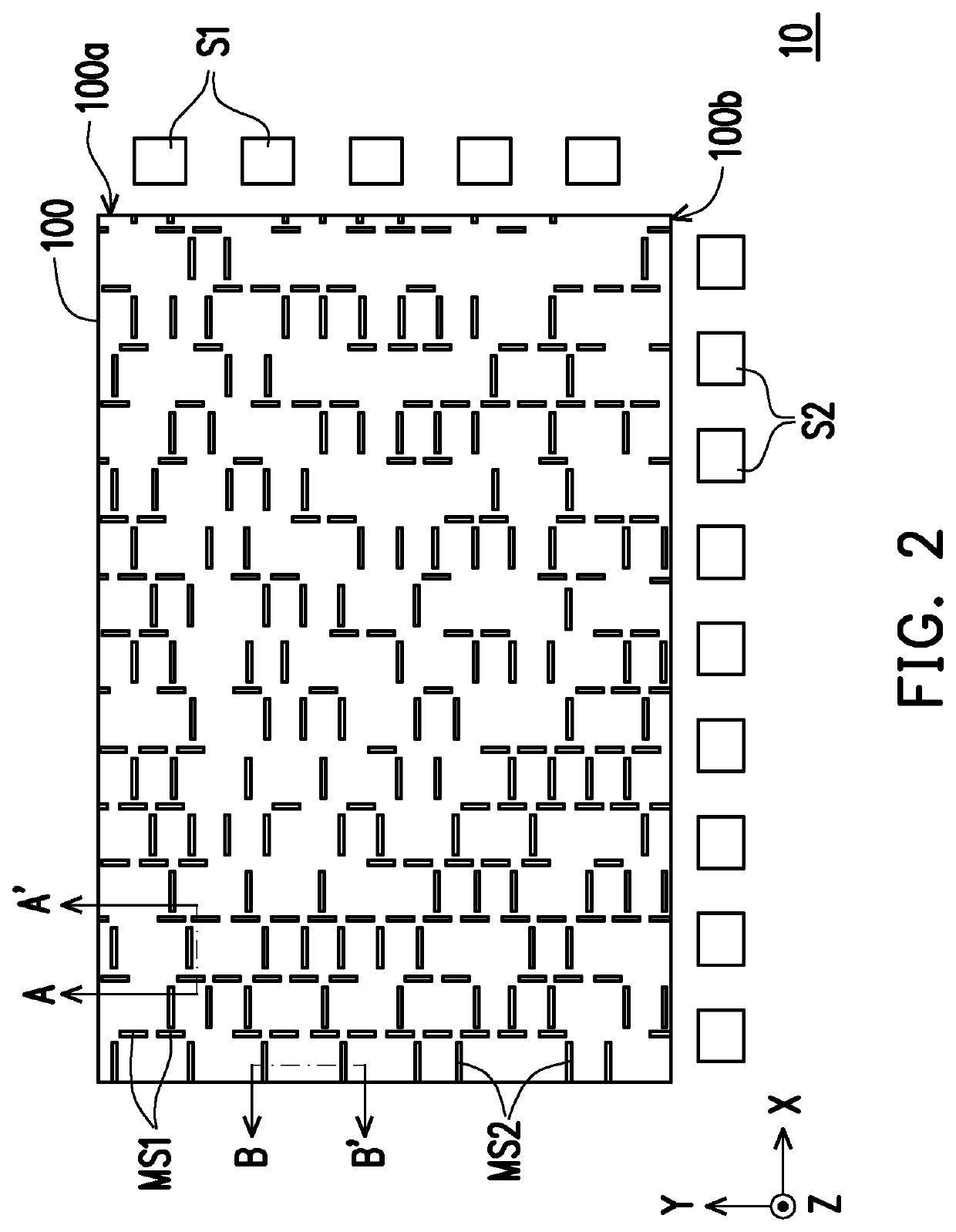
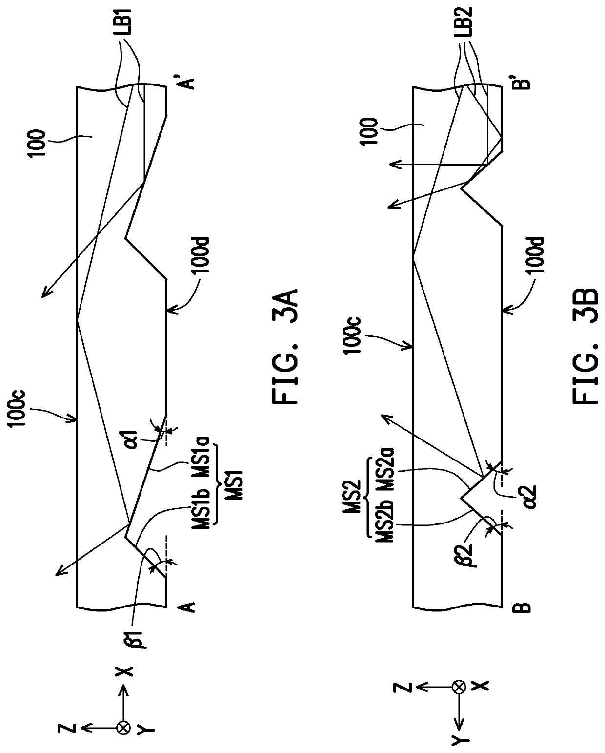
[0010]Based on the above, in the backlight module and the display apparatus according to an embodiment of the invention, the first light source and the second light source are provided at two adjacent light incident sides of the light guide member, respectively. The first light beam emitted by the first light source and the second light beam emitted by the second light source have the first light emitting angle range and the second light emitting angle range respectively after being reflected by the first optical microstructures and the second optical microstructures on the light guide member. The first light emitting angle range is less than the second light emitting angle range. Through switching between turning on and off of the first light source and the second light source, the backlight module may feature an adjustable light-emitting light type. In this way, the display apparatus can be switched between an anti-peep mode and a sharing mode, and convenience of operation of the display apparatus is therefore improved.

Problems solved by technology

However, during browsing of a private webpage and confidential information or entering of passwords in public, etc., the display apparatus has a wide viewing angle is likely to cause the confidential information to be viewed by others, resulting in leaking of the confidential information.
Therefore, it is an important issue for related manufacturer to develop a display apparatus exhibiting convenient viewing angle switch effect and a favorable anti-peep effect.

Method used


Image

  • Backlight module and display apparatus
  • Backlight module and display apparatus
  • Backlight module and display apparatus

Examples


first embodiment

[0027]FIG. 1 is a schematic view of a display apparatus according to the invention. FIG. 2 is a schematic top view of a backlight module in FIG. 1. FIG. 3A and FIG. 3B are schematic cross-sectional views of a first optical microstructure and a second optical microstructure in FIG. 2, respectively. FIG. 4 is a graph of a viewing angle versus normalized brightness of the backlight module of FIG. 1 in different modes. In particular, FIG. 3A and FIG. 3B correspond to a section line A-A′ and a section line B-B′ in FIG. 2, respectively. For clarity, FIG. 2 omits an optical film 110 and a light absorbing sheet 180 in FIG. 1.

[0028]Referring to FIG. 1, FIG. 2, FIG. 3A, and FIG. 3B, a display apparatus 1 includes a backlight module 10 and a display panel 50. The display panel 50 is overlapped with the backlight module 10. In the embodiment, the display panel 50 is, for example, a liquid crystal display panel (LCD panel), but the invention is not limited thereto. In other embodiments, the disp...

second embodiment

[0045]FIG. 5 is a schematic view of a display apparatus according to the invention. FIG. 6 is a graph of a viewing angle versus normalized brightness of a backlight module of FIG. 5 in different modes. Referring to FIG. 5, a main difference between a display apparatus 2 in the embodiment and the display apparatus 1 in FIG. 1 lies in different optical film numbers. In the embodiment, a backlight module 11 of the display apparatus 2 further includes an optical film 120 disposed between an optical film 110 and a display panel 50. For example, the optical film 120 includes a substrate 121 and a plurality of prism structures 122. The prism structures 122 are arranged on a side surface of the substrate 121 away from a light guide member 100 in a direction Y. In other words, the optical film 120 in the embodiment may be a prism sheet, but the invention is not limited thereto.

[0046]It is worth noting that the prism pillar structures 122 extend in a direction perpendicular to a first light i...

third embodiment

[0047]FIG. 7 is a schematic view of a display apparatus according to the invention. FIG. 8 is a graph of a viewing angle versus normalized brightness of a backlight module of FIG. 7 in different modes. Referring to FIG. 7, a main difference between a display apparatus 3 in the embodiment and the display apparatus 2 in FIG. 5 lies in different optical film numbers. In particular, a backlight module 12 of the display apparatus 3 includes, in addition to an optical film 120, an optical film 130 disposed between a light guide member 100 and the optical film 120. In the embodiment, the optical film 110 may be selectively disposed between a display panel 50 and the optical film 120, but the invention is not limited thereto.

[0048]For example, the optical film 130 includes a substrate 131 and a plurality of prism structures 132. The prism structures 132 are arranged on a side surface of the substrate 131 closer to a light guide member 100 in a direction Y. The prism structures 132 extend in...


PUM

PropertyMeasurementUnit
angleaaaaaaaaaa
angleaaaaaaaaaa
angleaaaaaaaaaa

Abstract

A backlight module includes a light guide member, a first light source, a second light source, a plurality of first optical microstructures, and a plurality of second optical microstructures. The light guide member has a first light incident surface and an adjacent second light incident surface. The first light source is disposed at one side of the first light incident surface and is configured to generate a first light beam. The second light source is disposed at one side of the second light incident surface and is configured to generate a second light beam. The first and the second optical microstructures are disposed at the light guide member and are configured to reflect the first and the second light beams. The reflected first light beam has a first light emitting angle range without a normal viewing angle range. A display apparatus using the backlight module is also provided.

Description

CROSS-REFERENCE TO RELATED APPLICATION[0001]This application claims the priority benefit of China application serial no. 201922343014.4, filed on Dec. 24, 2019. The entirety of the above-mentioned patent application is hereby incorporated by reference herein and made a part of this specification.BACKGROUND OF THE INVENTIONField of the Invention[0002]The invention relates to a viewing angle control technology, and in particular, to a backlight module and a display apparatus.Description of Related Art[0003]Generally, a display apparatus has a wide viewing angle, so that a plurality of viewers may view a screen together. However, during browsing of a private webpage and confidential information or entering of passwords in public, etc., the display apparatus has a wide viewing angle is likely to cause the confidential information to be viewed by others, resulting in leaking of the confidential information. In order to achieve an anti-peep effect, a light control film (LCF) is generally ...

Claims


Application Information

Patent Timeline
Patent Type & Authority Patents(United States)
IPC IPC(8): G02B6/00F21V8/00
CPCG02B6/0051G02B6/0016G02B6/0053G02B6/0068G02B6/0036G02B6/0076
Inventor LIAO, CHUN-CHIENCHEN, PING-YENLIU, YUNG-LUNGLEE, CHUN-WEI
Owner CORETRONIC
Learn More