Viewing angle switch module and display apparatus

a technology of viewing angle switch and display apparatus, which is applied in the direction of instruments, non-linear optics, optics, etc., can solve the problems of user leakage of private or confidential information, and achieve the effect of favorable large viewing angle filtering

Active Publication Date: 2022-05-03
CORETRONIC
View PDF16 Cites 1 Cited by
  • Summary
  • Abstract
  • Description
  • Claims
  • Application Information

AI Technical Summary

Benefits of technology

[0005]The invention provides a viewing angle switch module with favorable large viewing angle filtering effect.
[0006]The invention provides a display apparatus with favorable anti-peep performance.
[0010]In view of the above, the embodiments of the invention have at least one of the following advantages or effects. In the viewing angle switch module according to an embodiment of the invention, through the cooperation between an extending direction of the block walls of the viewing angle limiting device and an axial direction of the optical axis of the liquid crystal layer of the electrically controlled viewing angle switch device, a large viewing angle filtering effect can be effectively enhanced. In addition, the display apparatus according to an embodiment of the invention, due to adopting the viewing angle switch module of the aforementioned embodiment, has excellent convenience when switching between an anti-peep mode and a sharing mode, and a large viewing angle filtering ability thereof is conducive to improving the anti-peep effect of the display apparatus.

Problems solved by technology

However, in some situations or on some occasions, for example, when browsing a private website, viewing some confidential information, or entering a password, a user may be subjected to leak some private or confidential information due to the wide viewing angle of a display which may be viewed by others somewhere else.
Therefore, how to develop a display apparatus with convenient viewing angle switching and excellent anti-peep effect has become an important issue for the related manufacturers.

Method used


Image

  • Viewing angle switch module and display apparatus
  • Viewing angle switch module and display apparatus
  • Viewing angle switch module and display apparatus

Examples


first embodiment

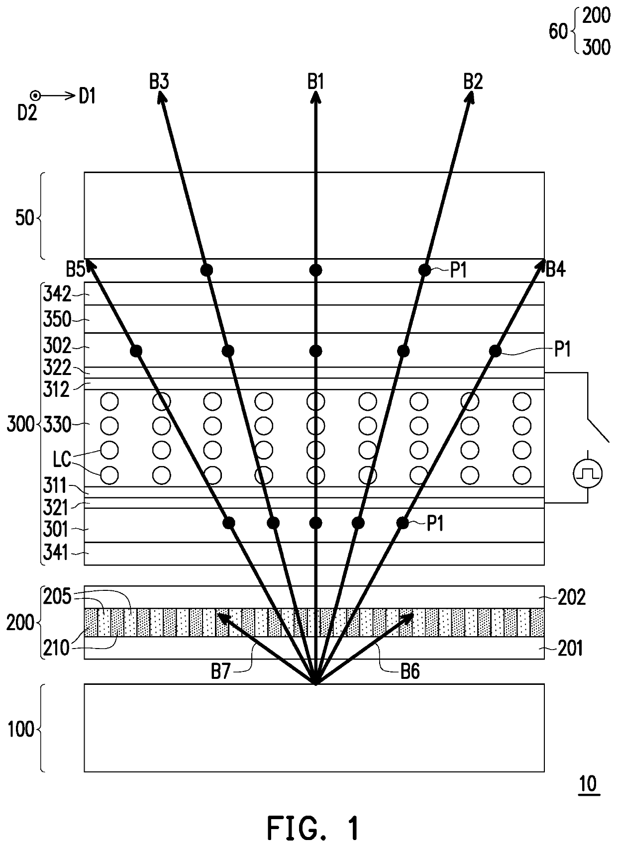
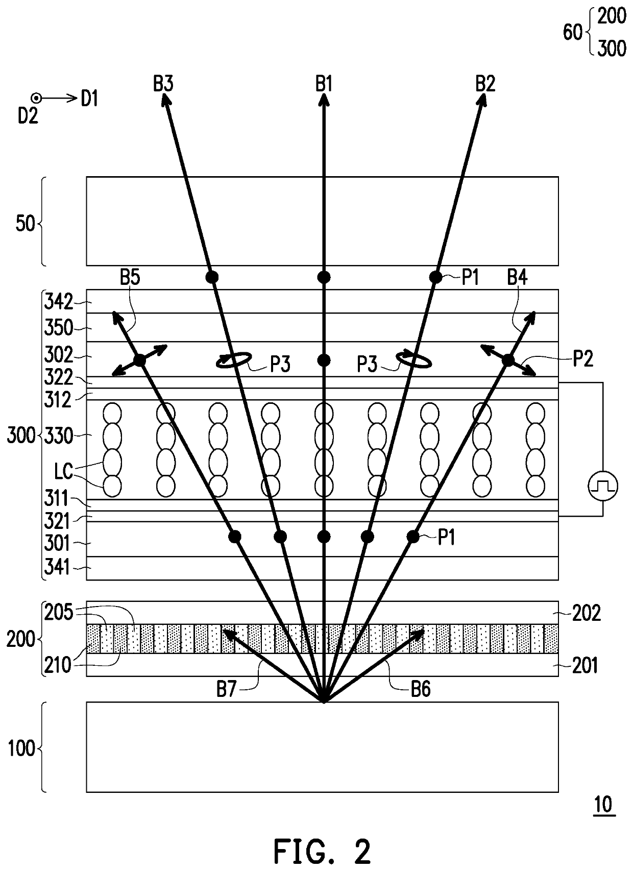
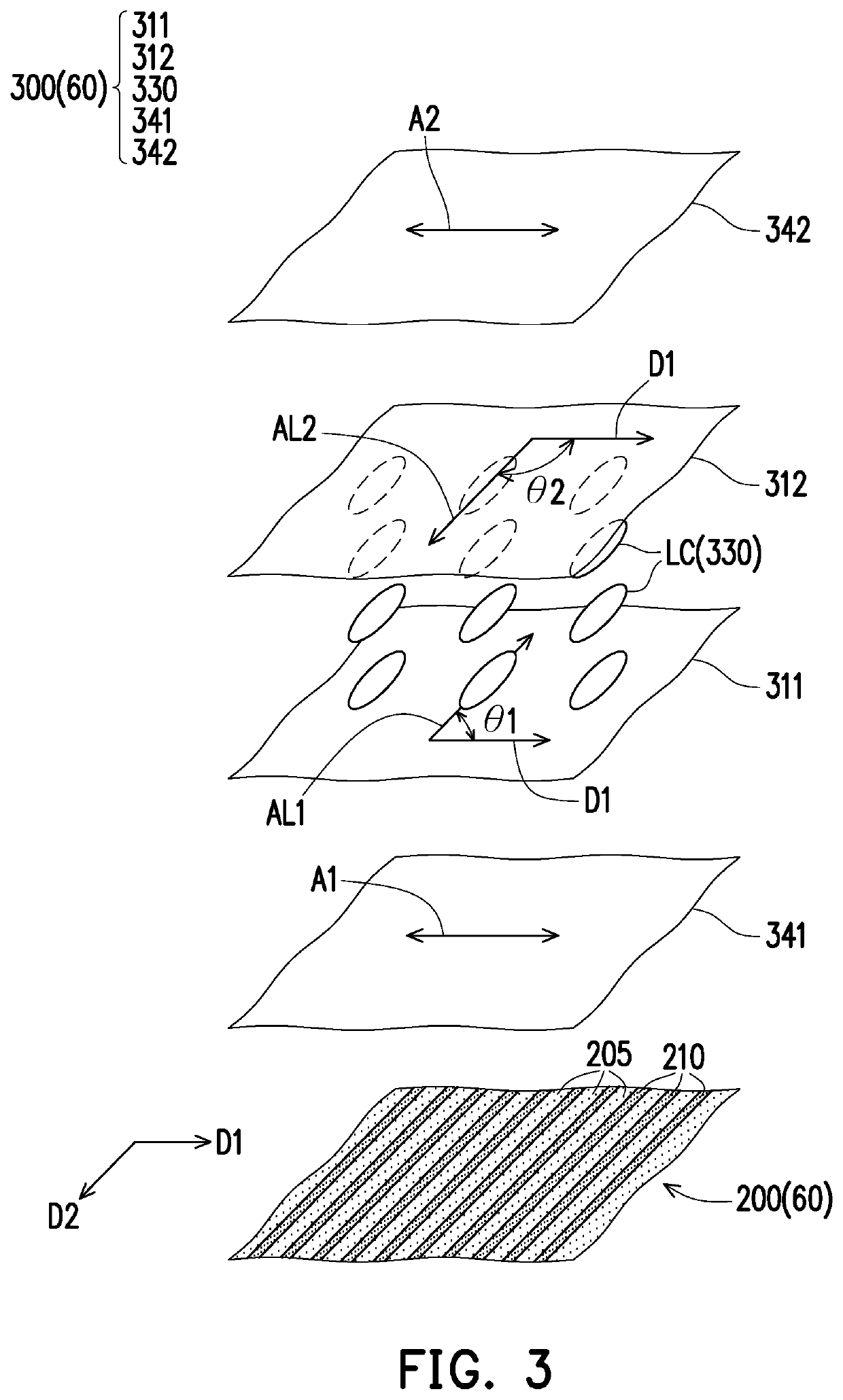
[0023]FIG. 1 and FIG. 2 are schematic cross-sectional views illustrating a display apparatus operating respectively under a sharing mode and an anti-peep mode according to the invention. FIG. 3 is schematic view illustrating a part of film layers of a viewing angle switch module of FIG. 1. FIG. 4 is a graph of viewing angle versus transmittance of an electrically controlled viewing angle switch device of FIG. 1. FIG. 5 is a schematic cross-sectional view of a backlight module of FIG. 1. It should be noted that, for clarity of presentation, FIG. 3 omits the illustrations of a plurality of substrates 201, 202, 301 and 302, two conductive layers 321 and 322 and a phase retardation film 350 of FIG. 1.

[0024]Referring to FIG. 1 and FIG. 3, a display apparatus 10 includes a display panel 50 and a viewing angle switch module 60, wherein the viewing angle switch module 60 enables the display apparatus 10 to be switchable between the sharing mode and the anti-peep mode. In the present embodim...

second embodiment

[0039]FIG. 6 is schematic view illustrating a part of film layers of a viewing angle switch module according to the invention. Referring to FIG. 6, a difference between the electrically controlled viewing angle switch device 300A of the present embodiment and the electrically controlled viewing angle switch device 300 of FIG. 3 lies in: the optical axis configuration of the liquid crystal layer 330 of the electrically controlled viewing angle switch device 300A. In the present embodiment, the angle θ1 included between the first alignment direction AL1 of the first alignment layer 311 of the electrically controlled viewing angle switch device 300A and the direction D1 may selectively be greater than 70 degrees and smaller than 90 degrees, and the angle θ2 included between the second alignment direction AL2 of the second alignment layer 312 and the direction D1 may selectively be greater than 70 degrees and smaller than 90 degrees. As such, the liquid crystal molecules LC of the liqui...

third embodiment

[0040]FIG. 7 is schematic view illustrating a part of film layers of a viewing angle switch module according to the invention. Referring to FIG. 7, a difference between the viewing angle limiting device 200A of the present embodiment and the viewing angle limiting device 200 of FIG. 3 lies in: the configuration of the block walls. In the present embodiment, the viewing angle limiting device 200A further includes a plurality of second block walls 220, and the second block walls 220 are arranged along the direction D2 and extended in the direction D1. That is, the second block walls 220 and the first block walls 210 intersect with each other. As such, the viewing angle switch module 60A can also provide a large angle filtering effect in the direction D2, and a display apparatus adopting the viewing angle switch module 60A can have in the direction D2 an anti-peep function that does not require electronically controlled switching, so as to meet the demands of different product designs....


PUM

PropertyMeasurementUnit
angleaaaaaaaaaa
transmittanceaaaaaaaaaa

Abstract

A viewing angle switch module including a viewing angle limiting device and a first electrically controlled viewing angle switch device is provided. A plurality of first block walls of the viewing angle limiting device are arranged along a first direction and extended in a second direction. The first electrically controlled viewing angle switch device has a first liquid crystal layer, a first polarizer and a second polarizer. An angle of 90±20 degrees is included between an optical axis of the first liquid crystal layer and the first direction. The first polarizer and the second polarizer are respectively located at two opposite sides of the first liquid crystal layer. An absorption axis of the first polarizer and a, absorption axis of the second polarizer are parallel to or perpendicular to the first direction. A display apparatus adopting the viewing angle switch module is also provided.

Description

CROSS-REFERENCE TO RELATED APPLICATION[0001]This application claims the priority benefit of China application serial no. 201910279017.8, filed on Apr. 9, 2019. The entirety of the above-mentioned patent application is hereby incorporated by reference herein and made a part of this specification.BACKGROUNDTechnical Field[0002]The invention relates to an optical module and a display apparatus, and particularly relates to a viewing angle switch module and a display apparatus.Description of Related Art[0003]Generally, a display device is usually designed to have a wide viewing angle for displaying so as to be viewed by multiple viewers. However, in some situations or on some occasions, for example, when browsing a private website, viewing some confidential information, or entering a password, a user may be subjected to leak some private or confidential information due to the wide viewing angle of a display which may be viewed by others somewhere else. Typically, in order to achieve an a...

Claims


Application Information

Patent Timeline
Patent Type & Authority Patents(United States)
IPC IPC(8): G02F1/13G02F1/1337G02F1/1335
CPCG02F1/1323G02F1/133528G02F1/133753G02F1/133757G02F1/133509G02F1/1337G02F1/13363G02F1/13471G02F1/133524G02F1/133531
Inventor FANG, CHUNG-YANGCHEN, PING-YENLIN, YANG-CHINGYU, JEN-WEICHEN, YU-FAN
Owner CORETRONIC
Why Eureka
Try Eureka