
Liquid crystal display panel

a liquid crystal display and display panel technology, applied in static indicating devices, instruments, non-linear optics, etc., can solve the problems of increasing the risk of data leakage, adversely affecting the optical property and display quality of the display device, and people aside the display device cannot clearly read the displayed image, etc., to achieve excellent anti-peeping effect, cost and process complexity are not increased

Active Publication Date: 2015-07-14
AU OPTRONICS CORP
View PDF15 Cites 1 Cited by
  • Summary
  • Abstract
  • Description
  • Claims
  • Application Information

AI Technical Summary

Benefits of technology

[0010]It is therefore one of the objectives of the present invention to provide a liquid crystal display panel to provide effective anti-peeping effect without increasing cost and process complexity.
[0015]The liquid crystal display panel of the present invention can provide excellent anti-peeping effect by modifying the pattern design of pixel electrode without changing or adding manufacturing process, and the cost and process complexity are not increased.

Problems solved by technology

However, under some circumstances, such as when reading confidential data or when inputting password, the wide viewing angle display effect makes it possible for other people around the display device to see the confidential data, which increases the risk of data leak.
The anti-peeping film can restrain the brightness of wider viewing angle, and thus people aside the display device cannot clearly read the displayed image.
The anti-peeping film is a commonly-used material, though; the additional anti-peeping film will adversely affects the optical property and display quality of the display device when displaying images for the user in front of the display device.
Also, the user has to manually switch the anti-peeping film, which causes inconvenience.
In practical application, it is difficult to control the light route, and thus a perfect collimated backlight cannot be obtained.
In such a case, the brightness of the backlight emitting in the side viewing direction may be reduced to a certain extent, but the brightness of the backlight emitting in the side viewing direction is yet not ignorable.
As a result, the anti-peeping effect is not satisfactory.
Also, the cost is highly increased.

Method used


Image

  • Liquid crystal display panel
  • Liquid crystal display panel
  • Liquid crystal display panel

Examples


Embodiment Construction

[0036]To provide a better understanding of the present invention to the skilled users in the technology of the present invention, preferred embodiments will be detailed as follows. The preferred embodiments of the present invention are illustrated in the accompanying drawings with numbered elements to elaborate the contents and effects to be achieved.

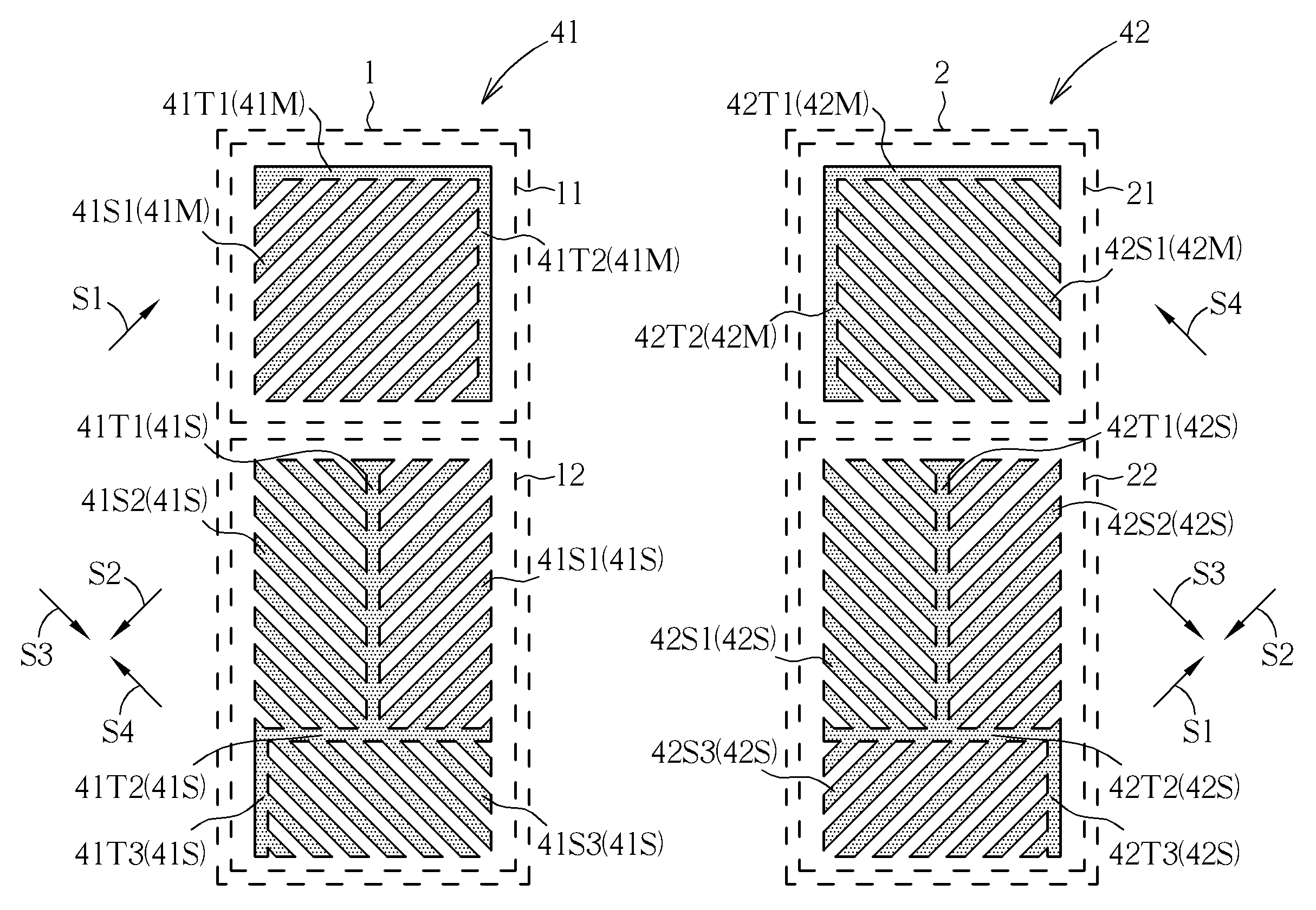
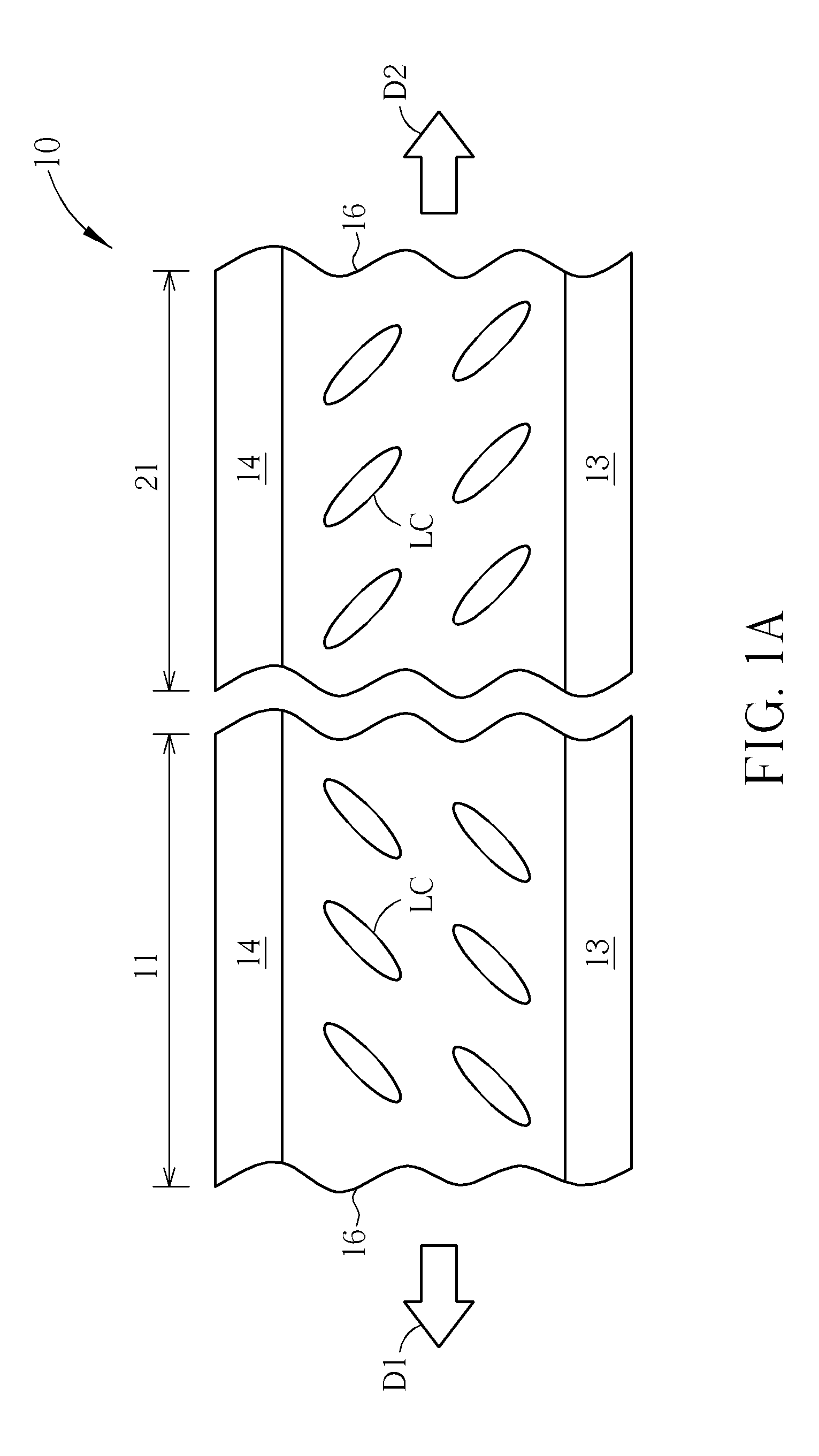
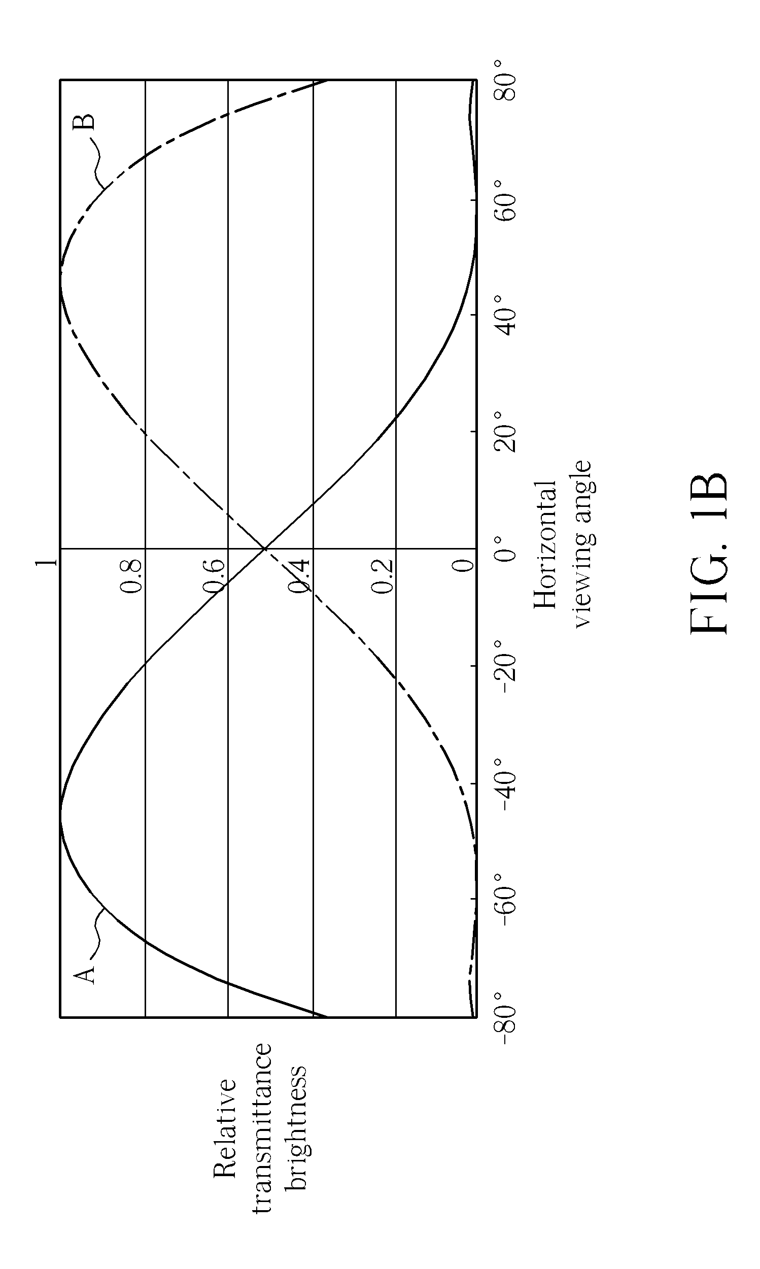
[0037]Please refer to FIG. 1A and FIG. 1B. FIG. 1A is a schematic diagram illustrating a liquid crystal display panel according to a preferred embodiment of the present invention, and FIG. 1B is a schematic diagram illustrating a relation between relative transmittance brightness and a horizontal viewing angle of a first main region and a second main region of the liquid crystal display panel of FIG. 1A. As shown in FIG. 1A, the liquid crystal display panel 10 of the present embodiment includes a first substrate 13, a second substrate 14, and a liquid crystal layer 16. The first substrate 13 and the second substrate 14 are disposed oppo...


PUM

PropertyMeasurementUnit
included angleaaaaaaaaaa

Abstract

A liquid crystal display panel includes a first substrate, a second substrate, a liquid crystal layer, a plurality of first regions and a plurality of second regions. The first regions and the second regions are formed on the first substrate and the second substrate. In a narrow viewing mode, the luminous flux of the first regions along a first viewing direction is different from that of the first regions along a second viewing direction opposite to the first viewing direction, and the luminous flux of the second regions along the first viewing direction is substantially different from that of the first regions along the first viewing direction.

Description

BACKGROUND OF THE INVENTION[0001]1. Field of the Invention[0002]The present invention relates to a liquid crystal display panel, and more particularly, to a liquid crystal display panel able to provide anti-peeping effect.[0003]2. Description of the Prior Art[0004]Generally, a display device is provided with wide viewing angle such that more users can see the images displayed by the display device. However, under some circumstances, such as when reading confidential data or when inputting password, the wide viewing angle display effect makes it possible for other people around the display device to see the confidential data, which increases the risk of data leak. Therefore, to fulfill the two different requirements of providing images for more users at the same time and reading confidential data in public place wherever necessary, a display device that can be switched between a wide viewing angle mode and a narrow viewing angle mode has been expected as a mainstream product in displ...

Claims


Application Information

Patent Timeline
Patent Type & Authority Patents(United States)
IPC IPC(8): G02F1/13G02F1/1337G02F1/1343
CPCG02F1/1323G02F1/133753G02F1/134363G09G2320/028G02F1/134345G02F1/134336G02F1/136286G02F1/1368
Inventor YEH, CHAO-WEILIAO, CHIEN-HUANGHSU, WEN-HAOTING, TIEN-LUNCHEN, CHAO-YUANSU, JENN-JIA
Owner AU OPTRONICS CORP
Learn More