Repeater with a chain wound on a cam

a chain wound and repeater technology, applied in the field of repeater mechanism, can solve the problems of extremely sophisticated horological complication of repeater and inability to perfectly maintain the frequency of the chimes, and achieve the effect of reducing the drive torqu

Active Publication Date: 2021-11-16
MONTRES BREGUET
View PDF6 Cites 0 Cited by
  • Summary
  • Abstract
  • Description
  • Claims
  • Application Information

AI Technical Summary

Benefits of technology

[0043]By means of the cam path, it is possible to offset variations in the drive torque generated by the mainspring on the barrel arbor, which makes it possible to minimise variations in the traction force generated on the chain by the pulley. This results in chimes of extremely regular frequency during the strike function.
[0045]Thus, for example, the pulley and the chain jointly form, on the cam path, a contact point whose distance to the barrel arbor decreases with the winding of the chain. In this case, the cam path can offset the decrease in drive torque generated by the mainspring.

Problems solved by technology

The repeater is an extremely sophisticated horological complication.
However, a precise measurement shows that despite the regulator, the frequency of the chimes is not perfectly constant.

Method used


Image

  • Repeater with a chain wound on a cam
  • Repeater with a chain wound on a cam
  • Repeater with a chain wound on a cam

Examples


Embodiment Construction

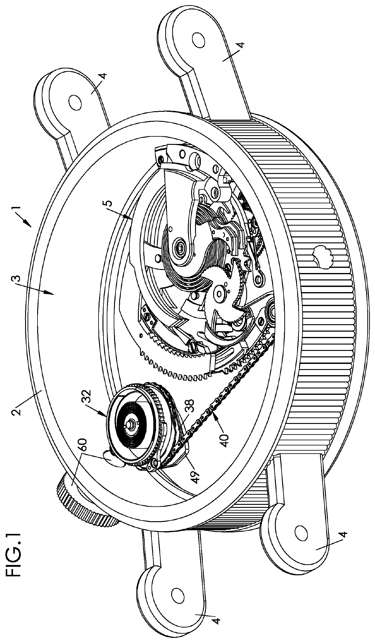
[0065]FIG. 1 partially represents a timepiece, in this case a watch 1. Watch 1 includes a case middle 2 which forms an internal volume 3. In the illustrated example, watch 1 is designed to be worn on the wrist, and its case middle 2 includes for this purpose projecting horns 4, to which a bracelet (not represented) is intended to be attached.

[0066]Watch 1 includes a timepiece movement designed to indicate at least the hours and minutes. The movement includes a mainplate intended to be housed inside internal volume 3 formed by case middle 2, and to be secured therein.

[0067]The movement further includes various functional components grouped into sub-assemblies. When a sub-assembly has a function other than displaying the hours, minutes and, if applicable, the seconds, it is called a ‘complication’.

[0068]Thus, the illustrated timepiece (i.e. watch 1) has a striking mechanism and, for the purpose of striking the current time, a repeater mechanism, also called a ‘repeater complication’ o...


PUM


Abstract

A repeater mechanism includes an hour snail, an hour rack carrying an hour beak and rotatably mounted about an hour axis between a rest position and a read position, an hour spring, which returns the hour rack to its read position, a pulley rotatably mounted about a pulley axis and which forms a spiral-shaped peripheral cam path, a chain able to be wound on the pulley, the chain being hooked on the pulley and on the hour rack, and a return spring coupled to the pulley and via which the pulley pulls the hour rack, via the chain, into its rest position.

Description

CROSS-REFERENCE TO RELATED APPLICATION[0001]This application claims priority to European Patent Application No. 17209993.9 filed on Dec. 22, 2017, the entire disclosure of which is hereby incorporated herein by reference.FIELD OF THE INVENTION[0002]The invention concerns the field of horology. It more specifically concerns a repeater mechanism for a striking timepiece; the term ‘timepiece’ preferably refers to watch (a wristwatch or fob watch) but may also refer to a pendulum or other clock.PRIOR ART[0003]The purpose of the repeater mechanism (usually simply called a ‘repeater’) is to strike, at the request of the user (or wearer)—by depressing a pusher at any time—the time indicated at that moment by the hands of the timepiece.[0004]The repeater is an extremely sophisticated horological complication. Formerly intended to allow the time to be determined in the dark, the repeater is nowadays fitted to high or extremely high value watches.[0005]There are several types of repeater. In ...

Claims


Application Information

Patent Timeline
Patent Type & Authority Patents(United States)
IPC IPC(8): G04B21/12G04B21/04
CPCG04B21/12G04B21/04G04B21/00
Inventor BIFRARE, CHRISTOPHEZAUGG, ALAIN
Owner MONTRES BREGUET
Why Eureka
Try Eureka