Resonator and resonance device
a resonance device and resonance technology, applied in the direction of impedence networks, electrical devices, etc., can solve the problems of anchor loss still occurring and anchor loss occurring accordingly, and achieve the effects of reducing anchor loss, increasing q factor, and increasing q factor of resonator
- Summary
- Abstract
- Description
- Claims
- Application Information
AI Technical Summary
Benefits of technology
Problems solved by technology
Method used
Image
Examples
first embodiment
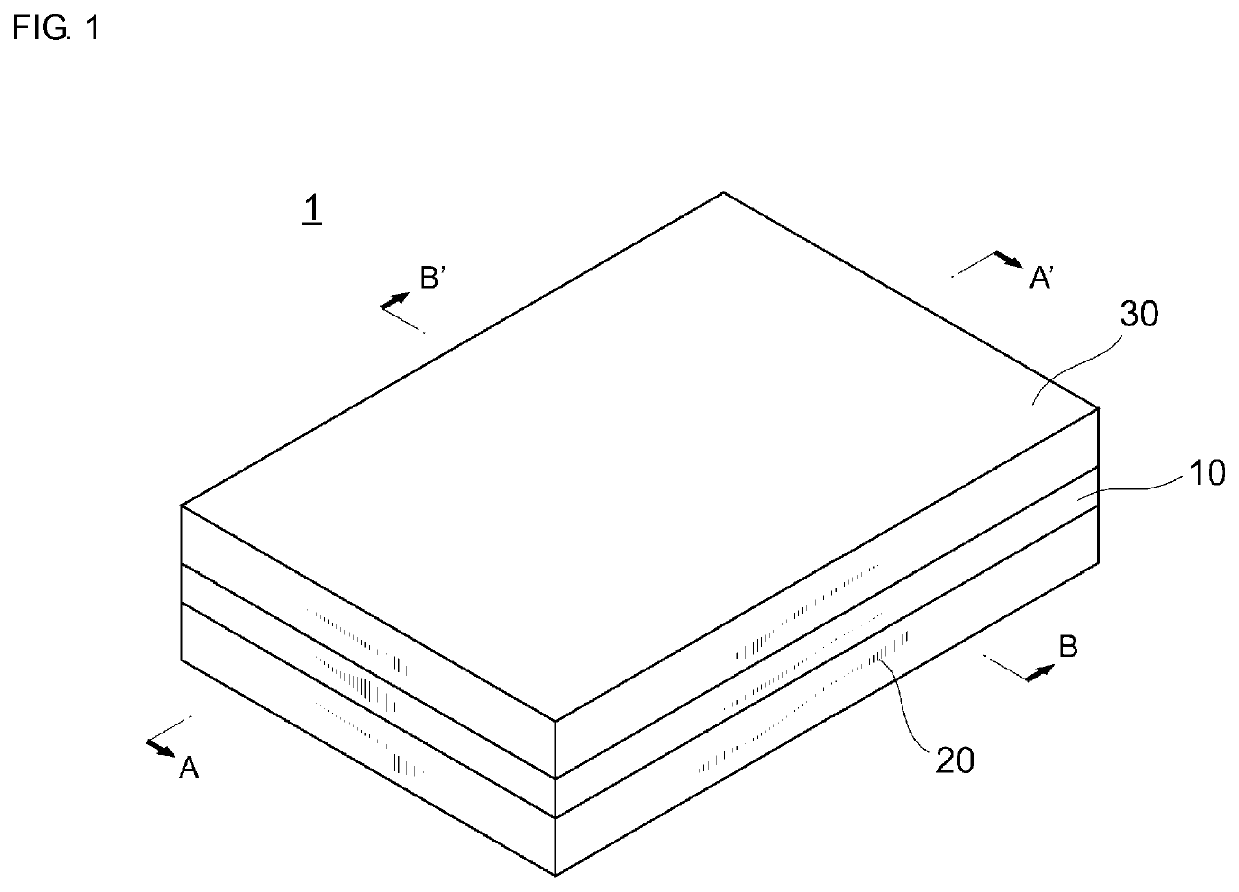
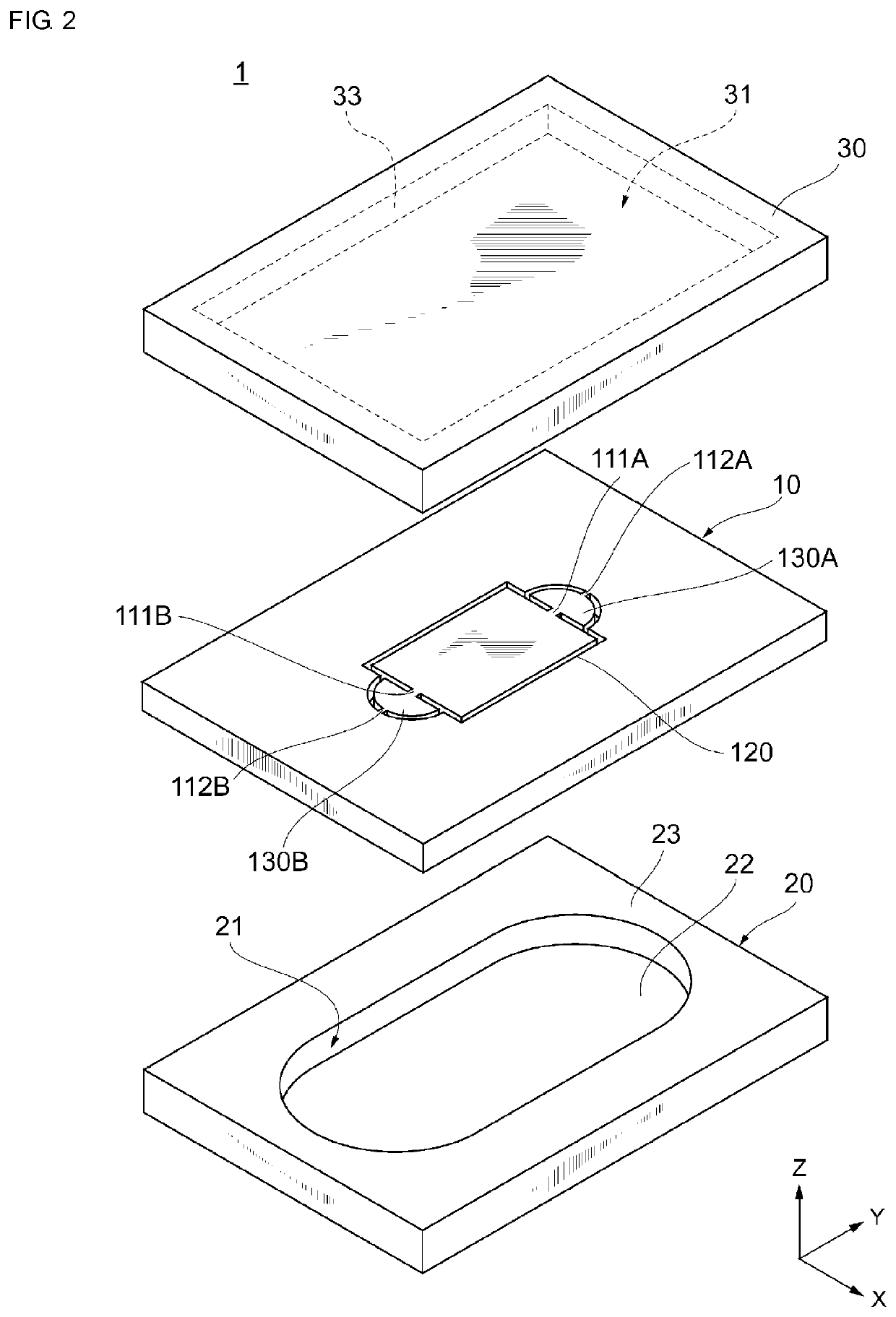
[0033]A first exemplary embodiment will now be described with reference to the accompanying drawings. FIG. 1 is a schematic perspective view illustrating the appearance of a resonance device 1 according to a first exemplary embodiment. FIG. 2 is a schematic exploded perspective view illustrating the structure of the resonance device 1 according to the first exemplary embodiment.
[0034]The resonance device 1 includes a resonator 10, an upper cover 30, and a lower cover 20. The resonator 10 is disposed between the upper cover 30 and the lower cover 20. In other words, the resonance device 1 is formed by laminating the lower cover 20, the resonator 10, and the upper cover 30 in that order.
[0035]The resonator 10, the lower cover 20, and the upper cover 30 are joined together so as to seal the resonator 10 and form a vibration space for the resonator 10. In an exemplary aspect, each of the resonator 10, the lower cover 20, and the upper cover 30 is formed by using a Si substrate. The reso...
second embodiment
[0096]In the second and following embodiments, description of matters that are the same as those in the first embodiment will be omitted, and only differences will be described. In particular, similar effects obtained by similar structures will not be described in each embodiment.
[0097]FIG. 8 illustrates an example of a plan view of a resonator 10 according to the second embodiment. The differences between the detailed structure of a resonance device 1 according to the present embodiment and that of the first embodiment will now be mainly described.
[0098]In the present embodiment, the node forming portions 130A and 130B have the shape of isosceles triangles having the connection sides 131a and 131b at the bases thereof. Other structures of the node forming portions 130A and 130B are similar to those in the first embodiment. Other structures and effects are similar to those in the first embodiment.
third embodiment
[0099]FIG. 9 illustrates an example of a plan view of a resonator 10 according to the present embodiment. The differences between the detailed structure of a resonance device 1 according to the present embodiment and that of the first embodiment will now be mainly described.
[0100](3-1) Vibrating Portion 120
[0101]In the present embodiment, the vibrating portion 120 has a pair of long sides 121c and 121d extending in the X-axis direction and a pair of short sides 121a and 121b extending in the Y-axis direction. The upper electrode E1 and the lower electrode E2 have short sides extending in the Y-axis direction and long sides extending in the X-axis direction. The vibrating portion 120 of the present embodiment causes in-plane vibration in the longitudinal direction. Other structures of the vibrating portion 120 are similar to those in the first embodiment.
[0102](3-2) Connecting Arms 111A and 111B
[0103]In the present embodiment, the connecting arm 111A is connected to a central portion...
PUM
 Abstract
Description
Claims
Application Information
 - R&D
- Intellectual Property
- Life Sciences
- Materials
- Tech Scout
- Unparalleled Data Quality
- Higher Quality Content
- 60% Fewer Hallucinations
Browse by: Latest US Patents, China's latest patents, Technical Efficacy Thesaurus, Application Domain, Technology Topic, Popular Technical Reports.
© 2025 PatSnap. All rights reserved.Legal|Privacy policy|Modern Slavery Act Transparency Statement|Sitemap|About US| Contact US: help@patsnap.com


