Resonator and resonance device

a resonance device and resonance technology, applied in the direction of impedence networks, electrical devices, etc., can solve the problems of anchor loss, no consideration of the direction perpendicular to vibration and the thickness direction of the vibrator, and anchor loss still occurs, so as to improve the q-factor and reduce the loss of anchors. , the effect of improving the q-factor

Active Publication Date: 2018-07-05
MURATA MFG CO LTD
View PDF0 Cites 3 Cited by
  • Summary
  • Abstract
  • Description
  • Claims
  • Application Information

AI Technical Summary

Benefits of technology

[0007]Accordingly, the resonator of the present disclosure has been made in view of the circumstances described above, and aims to improve the Q-factor by reducing the anchor loss in the resonator.
[0009]With the resonator described above, nodal points of vibration of the piezoelectric vibrating portion in the stacking direction can be generated on the node generating portion. Advantageously, this configuration reduces anchor loss produced when the vibrating portion is retained by the retainer, and makes it possible to improve the Q-factor.
[0012]The resonator preferably includes a plurality of first retaining arms and a plurality of second retaining arms, and the plurality of first retaining arms and the plurality of second retaining arms preferably connect to respective ones of the plurality of node regions. In this case, it is possible to further reduce anchor loss produced when the vibrating portion is retained by the retainer.
[0014]With this resonance device, anchor loss is reduced and it is possible to improve the Q-factor.
[0015]Advantageously, with the resonator according to the exemplary embodiments disclosed herein, the Q-factor can be improved by reducing anchor loss.

Problems solved by technology

In these resonators, where the vibrating portion is retained by the retaining arm, vibration leaks and this causes anchor loss.
However, no consideration has been given to the direction perpendicular to vibration and the direction of thickness of the vibrator.
As such, anchor loss still occurs.

Method used


Image

  • Resonator and resonance device
  • Resonator and resonance device
  • Resonator and resonance device

Examples


first embodiment

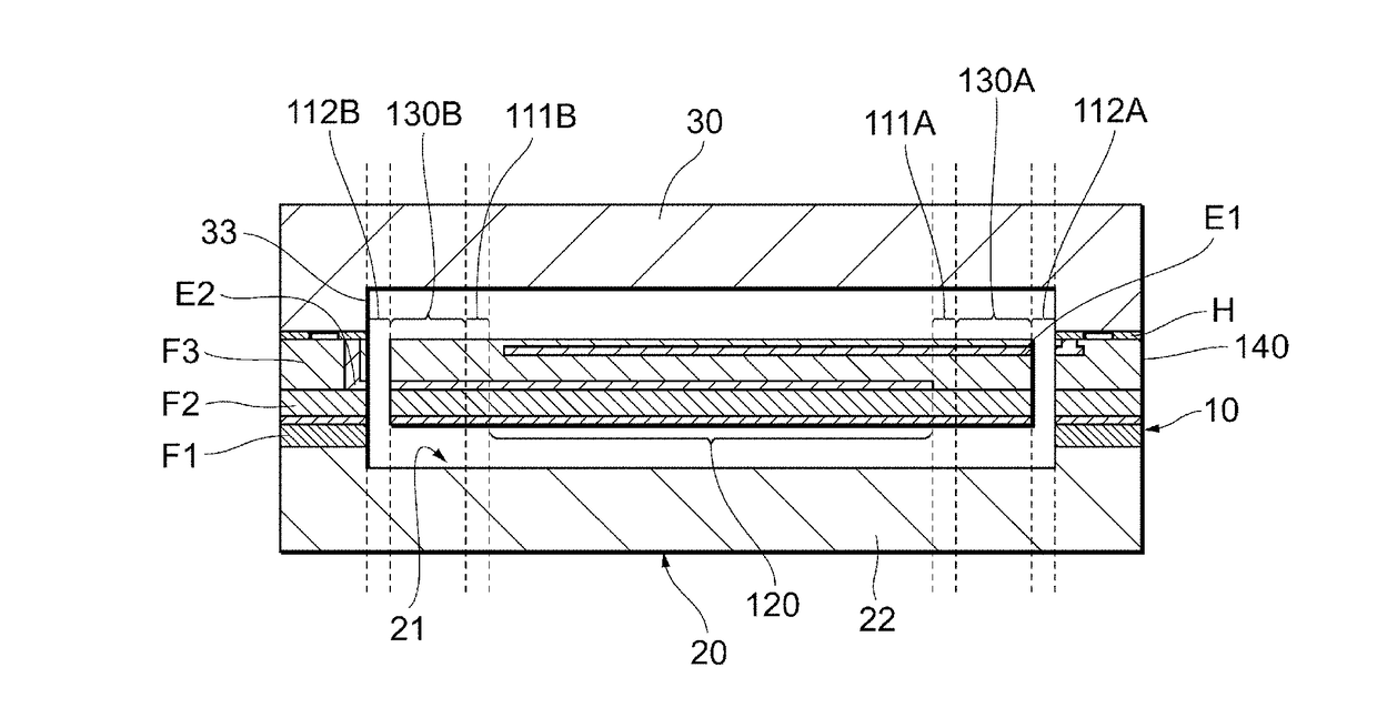
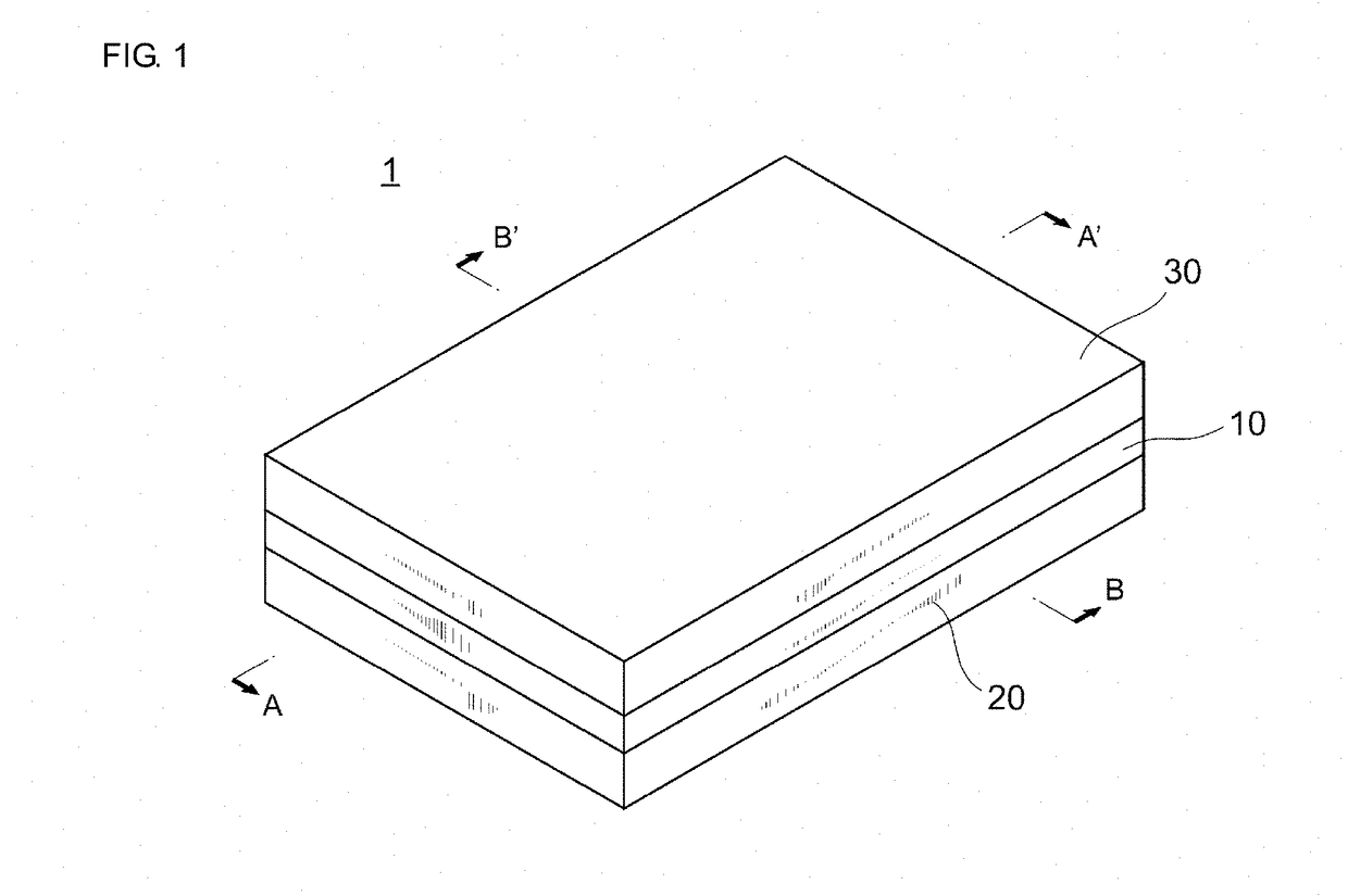
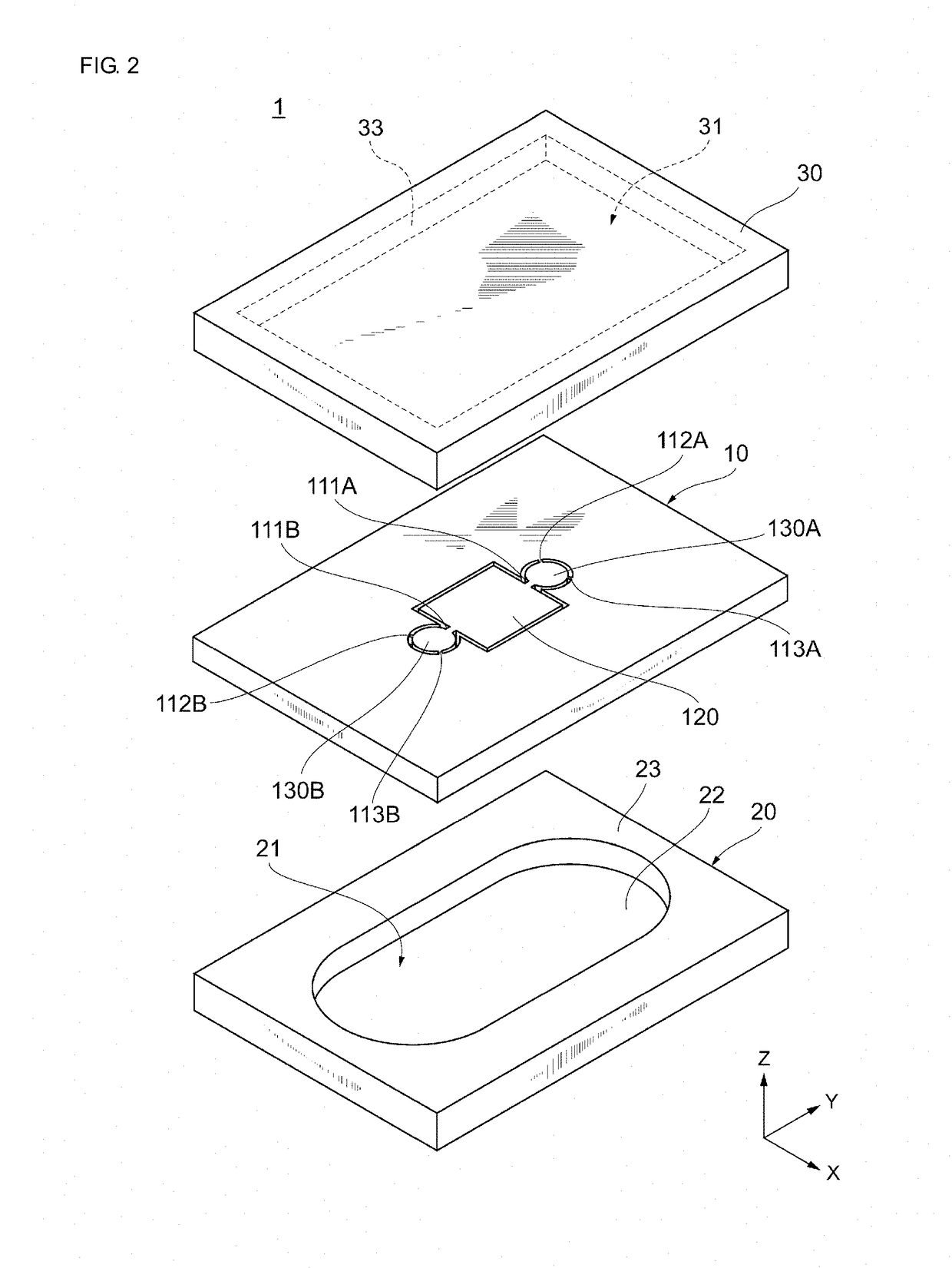
[0030]Hereinafter, a first exemplary embodiment will be described with reference to the attached drawings. FIG. 1 is a perspective view schematically illustrating an appearance of a resonance device 1 according to the first exemplary embodiment. FIG. 2 is an exploded perspective view schematically illustrating a structure of the resonance device 1 according to the first exemplary embodiment.

[0031]As generally shown, the resonance device 1 includes a resonator 10, and an upper cover 30 and a lower cover 20 provided with the resonator 10 interposed therebetween. That is, the resonance device 1 is formed by stacking the lower cover 20, the resonator 10, and the upper cover 30 in this order.

[0032]The resonator 10 is joined to the lower cover 20 and the upper cover 30. This seals the resonator 10 and forms a vibration space of the resonator 10. The resonator 10, the lower cover 20, and the upper cover 30 are each preferably formed using an Si substrate. The resonator 10, the lower cover ...

second embodiment

[0093]In second and subsequent embodiments, the explanation of matters common to those in the first embodiment will be omitted, and only differences will be explained. In particular, the same operational advantage achieved by the same configuration will not be mentioned one by one in each embodiment.

[0094]FIG. 8 is an exemplary plan view of the resonator 10 according to the second exemplary embodiment. Of details of the configuration of the resonance device 1 according to the present embodiment, differences from the first embodiment will be mainly described.

[0095](2-1) Node Generating Portions 130A, 130B

[0096]In the present embodiment, the node generating portion 130A is substantially square in shape. In the node generating portion 130A according to the present embodiment, a side 131a facing the short side 121a of the vibrating portion 120 is disposed parallel to the short side 121a. The length of each side of the node generating portion 130A is preferably set to about 50 μm. The ot...

third embodiment

[0104]FIG. 10 is an exemplary plan view of the resonator 10 according to the present embodiment. Of details of the configuration of the resonance device 1 according to the present embodiment, differences from the first embodiment will be mainly described.

[0105](3-1) Node Generating Portions 130A, 130B

[0106]In the present embodiment, the node generating portion 130A has a substantially diamond shape whose diagonals are along the Y-axis direction and the X-axis direction. Adjacent interior angles of the node generating portion 130A do not necessarily need to be equal. The configuration of the node generating portion 130B is the same as that of the node generating portion 130A. The other configurations of the node generating portions 130A and 130B are the same as those of the first embodiment.

[0107](3-2) Connecting Arms 111A, 111B

[0108]In the present embodiment, the connecting arm 111A connects at one end thereof to the node generating portion 130A at a vertex of the node generating po...


PUM


Abstract

A resonator that includes a piezoelectric vibrating portion; a retainer provided in at least part of an area surrounding the piezoelectric vibrating portion; a first node generating portion disposed between the piezoelectric vibrating portion and the retainer; a first connecting arm that connects the first node generating portion to a region in the piezoelectric vibrating portion that faces the first node generating portion; and a first retaining arm that connects the first node generating portion to a region in the retainer that faces the first node generating portion. The first node generating portion is substantially symmetrical with respect to each of two lines passing through a center of the first node generating portion along a first direction and a second direction orthogonal to the first direction, with the first direction being a direction that the first connecting arm connects the first node generating portion to the piezoelectric vibrating portion.

Description

CROSS REFERENCE TO RELATED APPLICATIONS[0001]The present application is a continuation of PCT / JP2016 / 068477 filed Jun. 22, 2016, which claims priority to U.S. Provisional Patent Application No. 62 / 221,308, filed Sep. 21, 2015, the entire contents of each of which are incorporated herein by reference.TECHNICAL FIELD[0002]The present disclosure relates to a resonator and a resonance device in which a vibrating portion vibrates in an in-plane vibration mode.BACKGROUND[0003]Conventionally, resonance devices using a micro electro mechanical systems (MEMS) technique have been used as timing devices, for example. Such resonance devices are mounted on a printed circuit board included in an electronic device, such as a smartphone. The resonance device includes a lower-side substrate, an upper-side substrate that forms a cavity with the lower-side substrate, and a resonator disposed in the cavity between the lower-side substrate and the upper-side substrate.[0004]For example, Patent Document ...

Claims


Application Information

Patent Timeline
Patent Type & Authority Applications(United States)
IPC IPC(8): H03H9/24H03H9/02H03H9/05H03H9/10
CPCH03H9/2405H03H9/02433H03H9/0595H03H9/1057H03H2009/0244H03H9/1035
Inventor NISHIMURA, TOSHIOKAAJAKARI, VILLE
Owner MURATA MFG CO LTD
Why Eureka
Try Eureka