Resonator and resonance device
a resonance device and resonance technology, applied in the direction of impedence networks, electrical devices, etc., can solve the problems of anchor loss, no consideration of the direction perpendicular to vibration and the thickness direction of the vibrator, and anchor loss still occurs, so as to improve the q-factor and reduce the loss of anchors. , the effect of improving the q-factor
- Summary
- Abstract
- Description
- Claims
- Application Information
AI Technical Summary
Benefits of technology
Problems solved by technology
Method used
Image
Examples
first embodiment
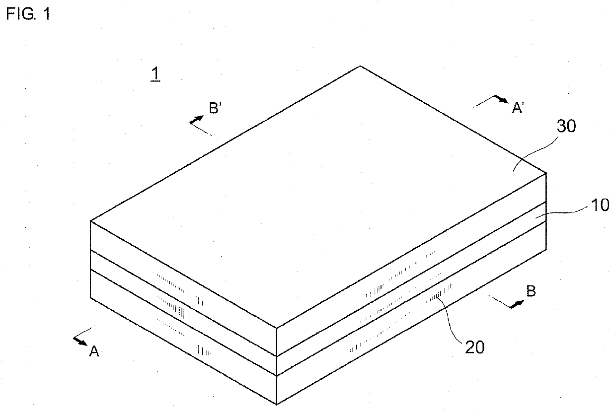
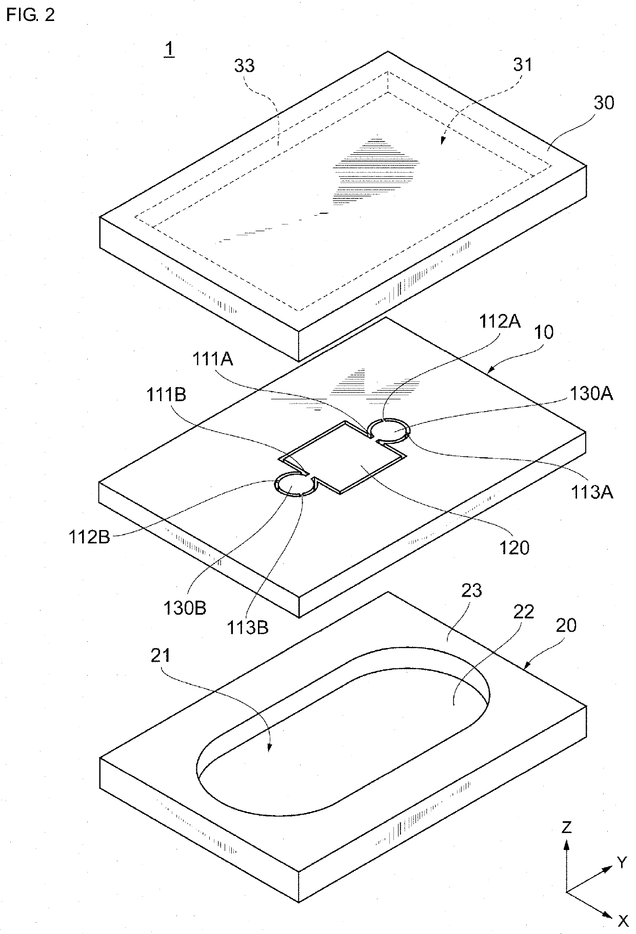
[0030]Hereinafter, a first exemplary embodiment will be described with reference to the attached drawings. FIG. 1 is a perspective view schematically illustrating an appearance of a resonance device 1 according to the first exemplary embodiment. FIG. 2 is an exploded perspective view schematically illustrating a structure of the resonance device 1 according to the first exemplary embodiment.
[0031]As generally shown, the resonance device 1 includes a resonator 10, and an upper cover 30 and a lower cover 20 provided with the resonator 10 interposed therebetween. That is, the resonance device 1 is formed by stacking the lower cover 20, the resonator 10, and the upper cover 30 in this order.
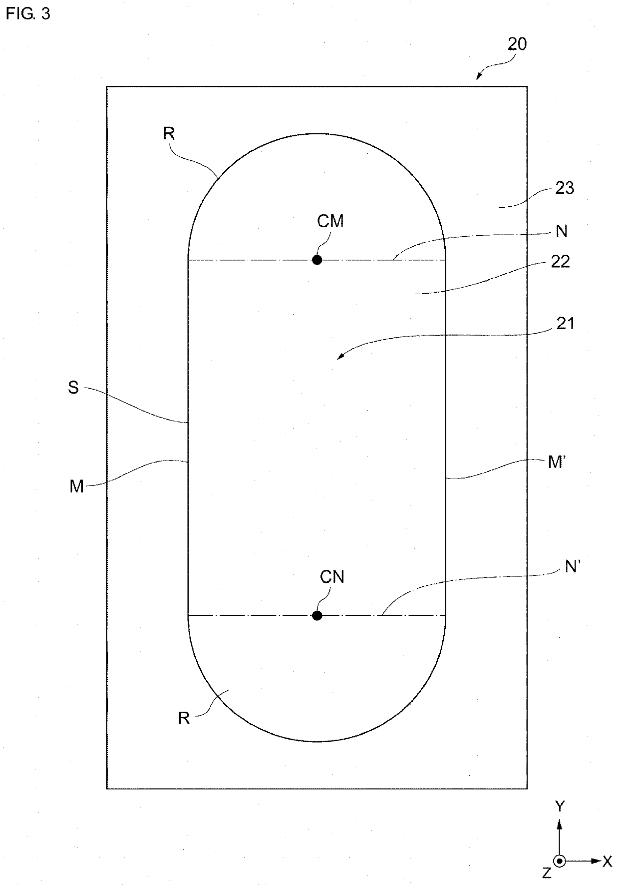
[0032]The resonator 10 is joined to the lower cover 20 and the upper cover 30. This seals the resonator 10 and forms a vibration space of the resonator 10. The resonator 10, the lower cover 20, and the upper cover 30 are each preferably formed using an Si substrate. The resonator 10, the lower cover ...
second embodiment
[0093]In second and subsequent embodiments, the explanation of matters common to those in the first embodiment will be omitted, and only differences will be explained. In particular, the same operational advantage achieved by the same configuration will not be mentioned one by one in each embodiment.
[0094]FIG. 8 is an exemplary plan view of the resonator 10 according to the second exemplary embodiment. Of details of the configuration of the resonance device 1 according to the present embodiment, differences from the first embodiment will be mainly described.
[0095](2-1) Node Generating Portions 130A, 130B
[0096]In the present embodiment, the node generating portion 130A is substantially square in shape. In the node generating portion 130A according to the present embodiment, a side 131a facing the short side 121a of the vibrating portion 120 is disposed parallel to the short side 121a. The length of each side of the node generating portion 130A is preferably set to about 50 μm. The ot...
third embodiment
[0104]FIG. 10 is an exemplary plan view of the resonator 10 according to the present embodiment. Of details of the configuration of the resonance device 1 according to the present embodiment, differences from the first embodiment will be mainly described.
[0105](3-1) Node Generating Portions 130A, 130B
[0106]In the present embodiment, the node generating portion 130A has a substantially diamond shape whose diagonals are along the Y-axis direction and the X-axis direction. Adjacent interior angles of the node generating portion 130A do not necessarily need to be equal. The configuration of the node generating portion 130B is the same as that of the node generating portion 130A. The other configurations of the node generating portions 130A and 130B are the same as those of the first embodiment.
[0107](3-2) Connecting Arms 111A, 111B
[0108]In the present embodiment, the connecting arm 111A connects at one end thereof to the node generating portion 130A at a vertex of the node generating po...
PUM
 Abstract
Description
Claims
Application Information
 - R&D
- Intellectual Property
- Life Sciences
- Materials
- Tech Scout
- Unparalleled Data Quality
- Higher Quality Content
- 60% Fewer Hallucinations
Browse by: Latest US Patents, China's latest patents, Technical Efficacy Thesaurus, Application Domain, Technology Topic, Popular Technical Reports.
© 2025 PatSnap. All rights reserved.Legal|Privacy policy|Modern Slavery Act Transparency Statement|Sitemap|About US| Contact US: help@patsnap.com


