Weather guard for a power boat

a technology for power boats and weather guards, which is applied in the direction of clear-view screens, waterborne vessels, vessel construction, etc., can solve the problems of inability to deploy snaps and zippers, limited utility of panels, and inability to protect the center consol

Active Publication Date: 2022-06-14
BECKE ALAN E +1
View PDF2 Cites 5 Cited by
  • Summary
  • Abstract
  • Description
  • Claims
  • Application Information

AI Technical Summary

Problems solved by technology

These panels have limited utility as they are inherently slow to deploy and must be stored on board when not in use, taking up valuable space.
Moreover, marine canvas shrinks, resulting in a fit that becomes tighter over time, and ultimately will result in failure of the snaps and zippers due to stress.
Torn canvas is another problem associated with these protective devices.
Beyond the issues with deploying these devices and their wear over time, most configurations do not offer full protection from the deck to the underside of the top structure, nor do they offer full protection across the beam of the vessel.
They are not rapidly deployable nor are they stowable.
When they are stowed, they require storage in a portion of the boat and can incur damage from scratches, mold, and mildew, and the like.
Though the above devices have their advantages, they also have drawbacks as previously discussed.

Method used


Image

  • Weather guard for a power boat
  • Weather guard for a power boat
  • Weather guard for a power boat

Examples


first embodiment

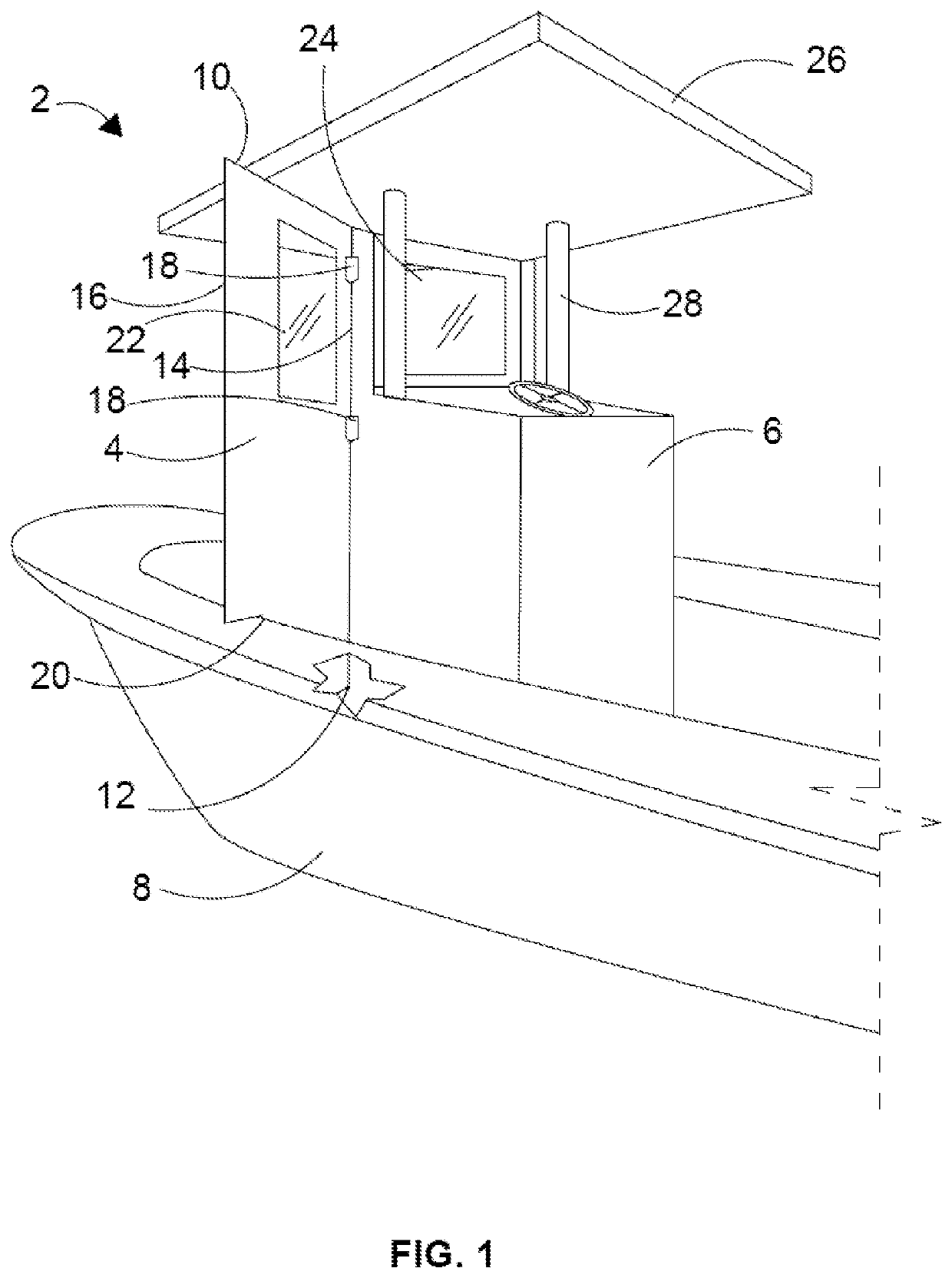
[0025]the weather guard 2 is shown in FIG. 1 and includes a protective shield 4 pivotably connected with the center console 6 of a boat 8. The shield has a top edge 10, bottom edge 12, first side edge 14 and second side edge 16. There are two hinge assemblies 18 connecting the first side edge with the center console for pivotable movement between open and closed positions. In FIG. 1, the shield is in its open position.

[0026]When in the open position, the second side edge 16 of the shield contacts the boat gunwale 20, blocking the entirety of the port side of the boat which in turn prevents adverse weather from reaching occupants behind the shield 4. The shield preferably contains a window 22 which allows boat occupants to view conditions in front of the boat when the shield is in its open position. In addition to the protective shield, the weather guard 2 includes a windshield 24 and T-top 26 connected to a frame 28.

[0027]As shown inFIG. 1, the second side edge 16 of the shield 4 is...

second embodiment

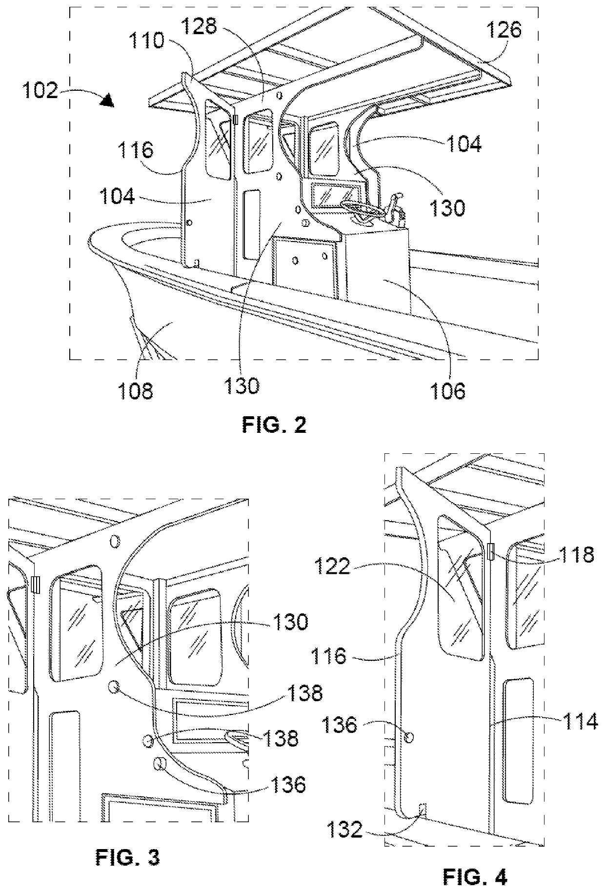
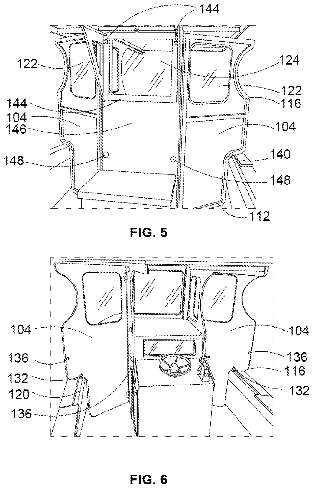
[0028]Referring now to FIGS. 2-9, the weather guard 102 is shown. In this embodiment, a frame 128 configured for connection with the center console 106 of the boat 108 is provided, and a pair of protective shields 104 are pivotably connected with the frame via hinge assemblies 118. As with the embodiment in FIG. 1, each of the protective shields has a top edge 110, a bottom edge 112, a first side edge 114, a second side edge 116, and a window 122.

[0029]The frame has two side walls 130 to which the protective shields 104 connect. The first side edge 114 of each shield is pivotably connected with its respective side wall, rather than directly with the boat. Each protective shield includes a lock assembly 132 for securing the shield with a boat gunwale 120, and a connection device 136 for securing the shield with the side walls 130 when the shield is in its closed position. The frame side walls include rubber stoppers 138 against which each protective shield rests when in its closed po...


PUM


Abstract

A rigid weather guard for a center console of a power boat includes a rapidly deployable protective shield. The shield has a top edge, a bottom edge, a first side edge that is pivotably connectable with a portion of the boat, and a second side edge that is configured for connection with a gunwale of the power boat. The pivotable connection of the first side edge provides movement between an open and closed position. When in the open position, the second side edge is connected with the gunwale securing the shield in place to block adverse weather. Preferably, the protective shield has a transparent portion.

Description

[0001]This application claims the benefit of U.S. provisional patent application No. 62 / 876,844 filed Jul. 22, 2019.BACKGROUND OF THE DISCLOSURE[0002]The present disclosure relates generally to a weather protection apparatus for a power boat, and more specifically to a weather guard for a center console of power boat.[0003]Many commercial and recreational power boats are open-air boats that do not include a roof, either as a portion or as the entirety of the boat. Such boats come equipped with, or can be modified to include, weather protective devices to shield individuals from adverse marine conditions.[0004]Windshields are one example of such a device found on many open-air power boats. These are typically made of clear acrylic or glass and are often mounted to the forward face of the boat helm console. Often, a tubular superstructure which straddles the console is employed to which the windshield is mounted. This structure can also carry a hard top or T-top which provides shade t...

Claims


Application Information

Patent Timeline
Patent Type & Authority Patents(United States)
IPC IPC(8): B63B17/02
CPCB63B17/02B63B2017/026B63B19/02
Inventor BECKE, ALAN E.BECKE, JESSE A.
Owner BECKE ALAN E
Why Eureka
Try Eureka