
Guard for a latch to prevent opening

a technology of latches and guards, which is applied in the direction of building locks, constructions, construction fastening devices, etc., can solve the problems of not solving the problem and not revealing the locking pin

Active Publication Date: 2022-06-28
CASTERNOVIA SAM
View PDF31 Cites 0 Cited by
  • Summary
  • Abstract
  • Description
  • Claims
  • Application Information

AI Technical Summary

Benefits of technology

[0009]It is an object of the present invention to provide a locking guard which is placed over a door latch to make it secure, so that the door latch cannot be unlatched from outside the door.
[0010]It is another object of the present invention to provide a locking guard having a notch which is placed over the door latch to make it secure, so that the door latch cannot be unlatched from outside the door.
[0012]Another object of the present invention is to provide a locking guard which is inexpensive and easy to install, and easy to remove from the door latch.
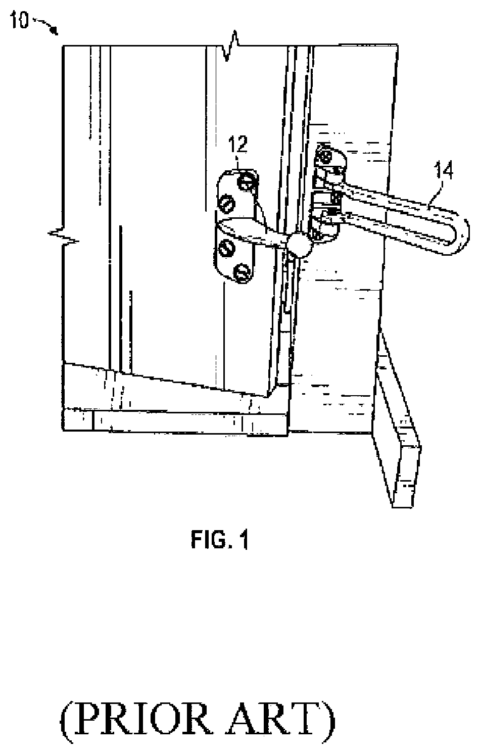
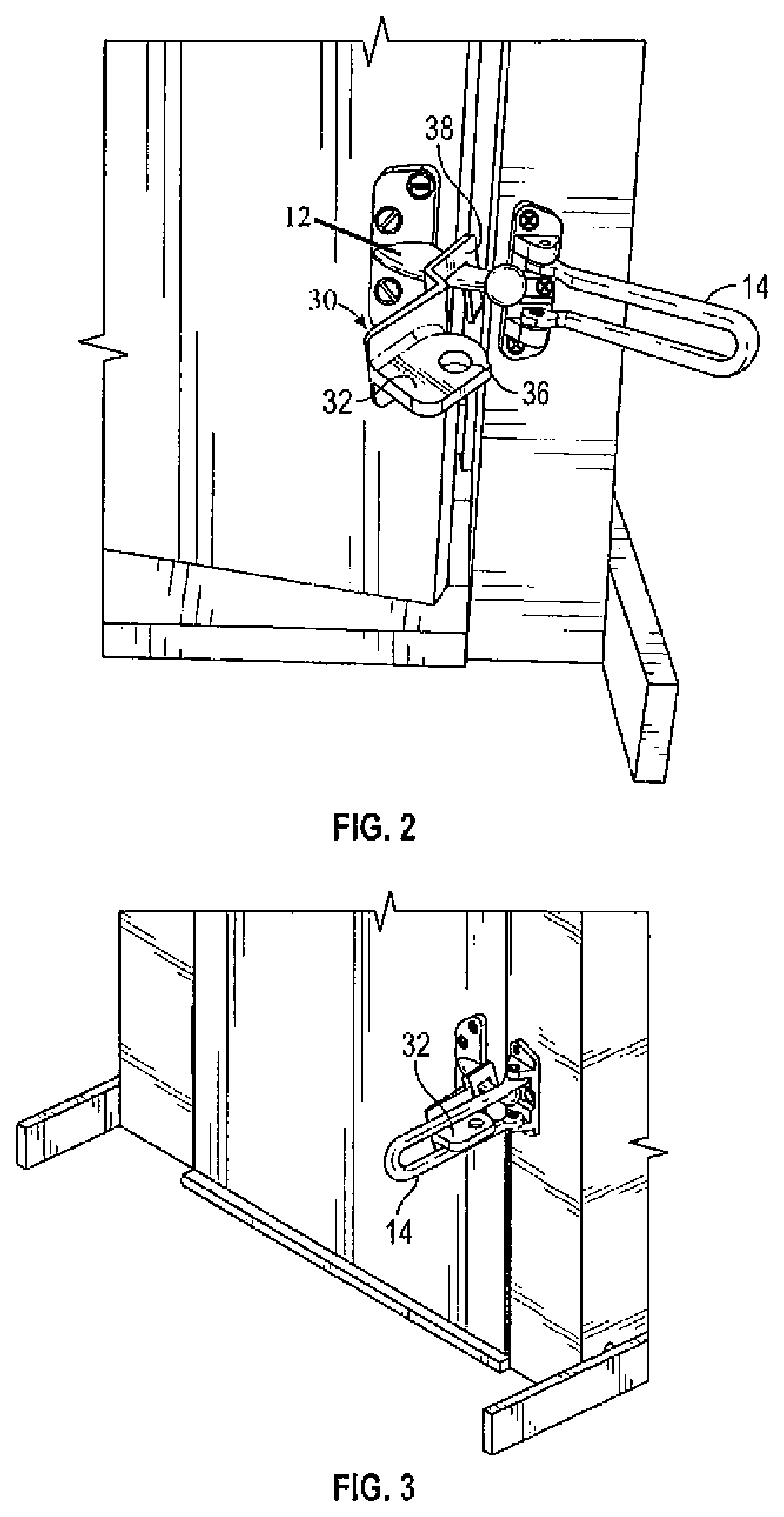
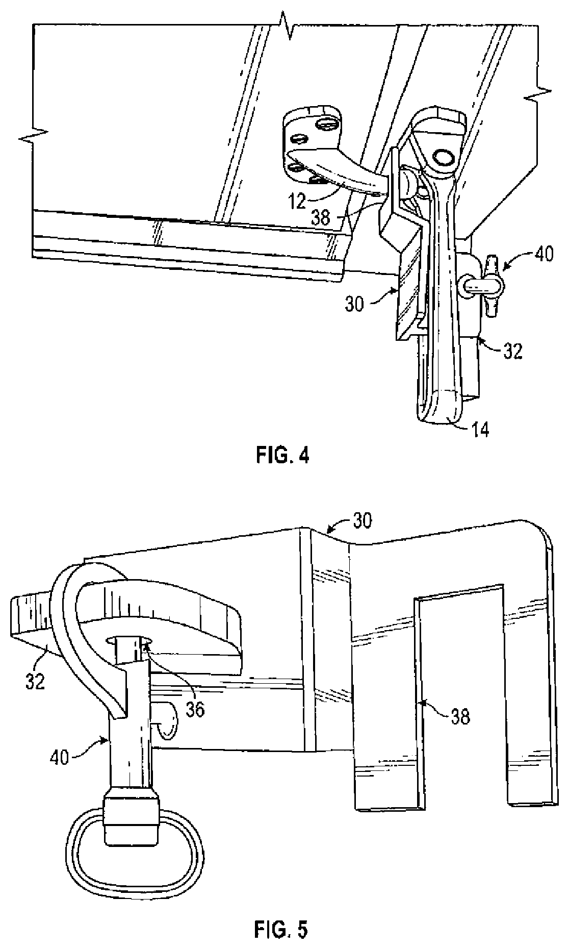
[0014]A door latch locking guard 30 is provided for maintaining a door in a locked position. A door latch 10 has an existing stationary latch arm 12 and the door jamb has an existing swinging arm 14 for engaging the latch arm 12 to lock the door. The present invention provides a protective locking guard 30 having a notch 38 formed therein for placing over the stationary latch arm 12, and the protective locking guard 30 also has a plate 32 for moving the existing swinging arm 14 over the plate 32. A locking clasp 40 is provided for inserting through an opening 36 in plate 32 in order to prevent the door latch 10 from being opened from the opposite side of the door.

Problems solved by technology

There are a number of prior art patents that provide improved door latches, but they have not solved the problem.
However, the '035 patent application to Yamashita does not disclose a locking pin for inserting through an opening in a locking guard and a plate for passing through the swinging arm.

Method used


Image

  • Guard for a latch to prevent opening
  • Guard for a latch to prevent opening
  • Guard for a latch to prevent opening

Examples


Embodiment Construction

[0020]As shown in FIGS. 2 to 4, the present invention provides a protective locking guard 30, which includes a flat horizontal plate 32 and also includes a notch 38 for placing over and engaging the latch arm 12. Specifically, the locking guard 30 includes an elongated vertical stepped plate for releasably securing the locking guard 30 to the existing stationary latch arm 12 and to the existing swinging arm 14. As shown, in FIGS. 2 to 5, the locking guard 30 is completely portable and can be secured to typical door latch security devices 10 without the need for mounting the locking guard using any additional fasteners, e.g., threaded fasteners. The locking guard 30 has a step-up portion at one end and a step-down portion at the other end, wherein the vertical height of the step-down portion can be more than the height of the step-up portion. Also, the step-up portion and the step-down portion are preferably positioned at an angle of greater than 90 degrees with respect to each other...


PUM


Abstract

A door latch locking guard 30 is provided for maintaining a door in a locked position. A door latch 10 has an existing stationary latch arm 12 and the door jam has an existing swinging arm 14 for engaging the latch arm 12 to lock the door. The present invention provides a protective locking guard 30 having a notch 38 formed therein for placing over the stationary latch arm 12, and the protective locking guard 30 also has a plate 32 for moving the existing swinging arm 14 over the plate 32. A locking clasp 40 is provided for inserting through an opening 36 in plate 32 in order to prevent the door latch 10 from being opened from the opposite side of the door.

Description

FIELD OF THE INVENTION[0001]This invention relates to a locking guard that is placed on an existing stationary door latch arm 12 to prevent the door latch from being opened by a person on the other side of the door.BACKGROUND OF THE INVENTION[0002]Door latches are typically used to lock a door, and also allows the door to be partially opened without opening the latch. The typical latch includes a fixed latch arm 12 mounted on the door, and a swinging arm 14 which is mounted next to the door and is moved to engage the latch arm 12 to lock the door.[0003]The problem with such door latches is that they are not secure, since devices have been developed that can be slid through the door crack to unlock the latch from outside the door.[0004]The present invention has been developed to solve this problem, by preventing someone outside the door from inserting a device to open the door latch.DESCRIPTION OF THE PRIOR ART[0005]There are a number of prior art patents that provide improved door l...

Claims


Application Information

Patent Timeline
Patent Type & Authority Patents(United States)
IPC IPC(8): E05C17/16E05B15/12E05C19/18
CPCE05C17/166E05B17/2023E05C19/184
Inventor CASTERNOVIA, SAM
Owner CASTERNOVIA SAM
Learn More