Speedometer gear output structure

Inactive Publication Date: 2005-09-08
SU KUO HSIN +2
View PDF6 Cites 5 Cited by
  • Summary
  • Abstract
  • Description
  • Claims
  • Application Information

AI Technical Summary

Benefits of technology

[0009] The present invention has been accomplished under the circumstances in view. It is one object of the present invention to provide a speedometer gear output structure, which is practical for use with an electronic speedometer. It is another object of the present invention to provide a speedometer gear output structure, which is durable in use. It is still another object of the present invention to provide a speedometer gear output structure, which is easy and inexpensive to install. To achieve these and other objects of the present invention, the speedometer gear output structure comprises a gearbox fastened to the front fork of a motorcycle, the gearbox comprising a driven gear rotatable with the wheels of the motorcycle, an output gear meshed with the driv

Problems solved by technology

This design is a mechanical design not suitable for use with an electronic speedometer.
The parts of the mechanical speedometer driving structure wear quickl

Method used


Image

  • Speedometer gear output structure
  • Speedometer gear output structure
  • Speedometer gear output structure

Examples


Embodiment Construction

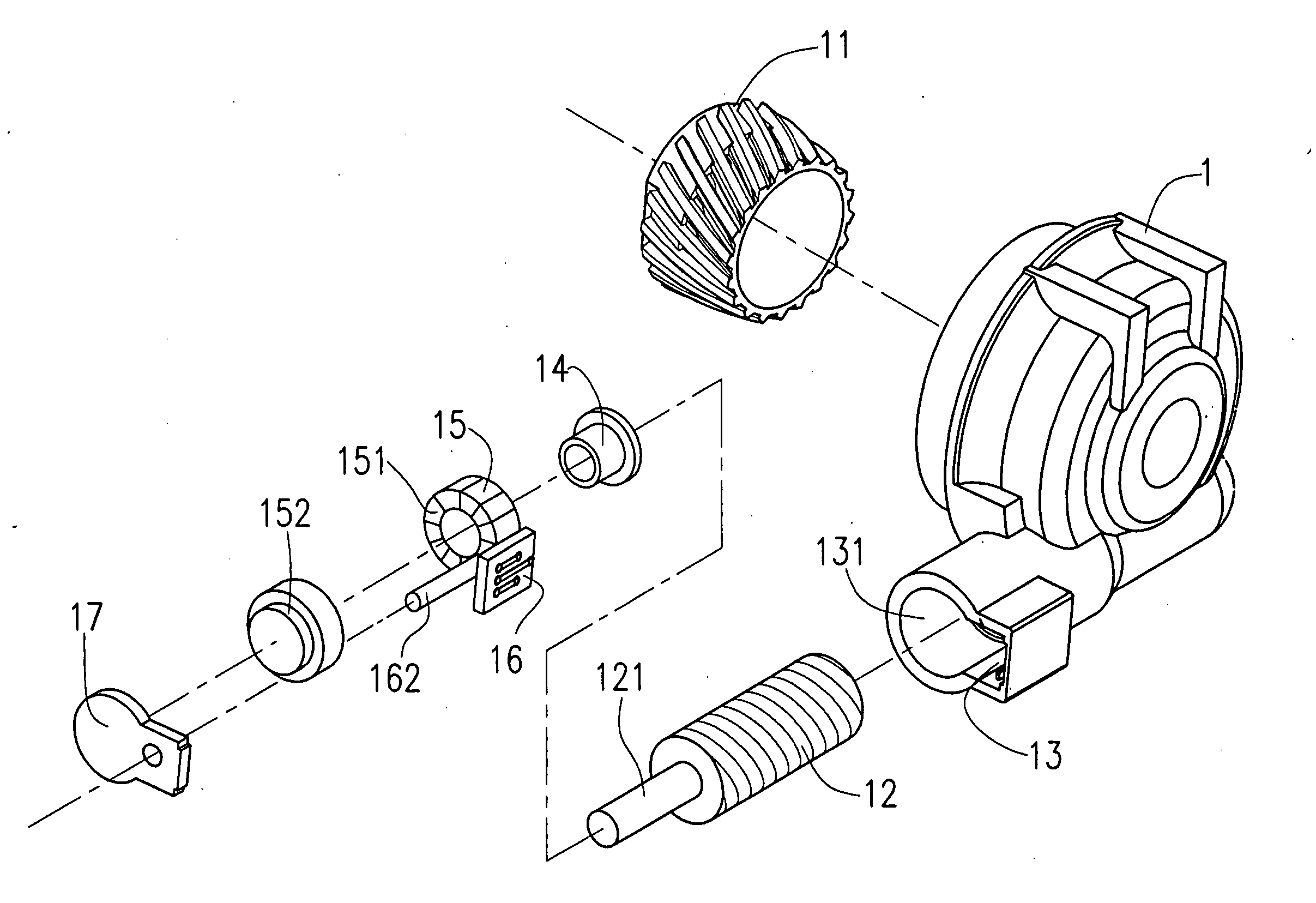
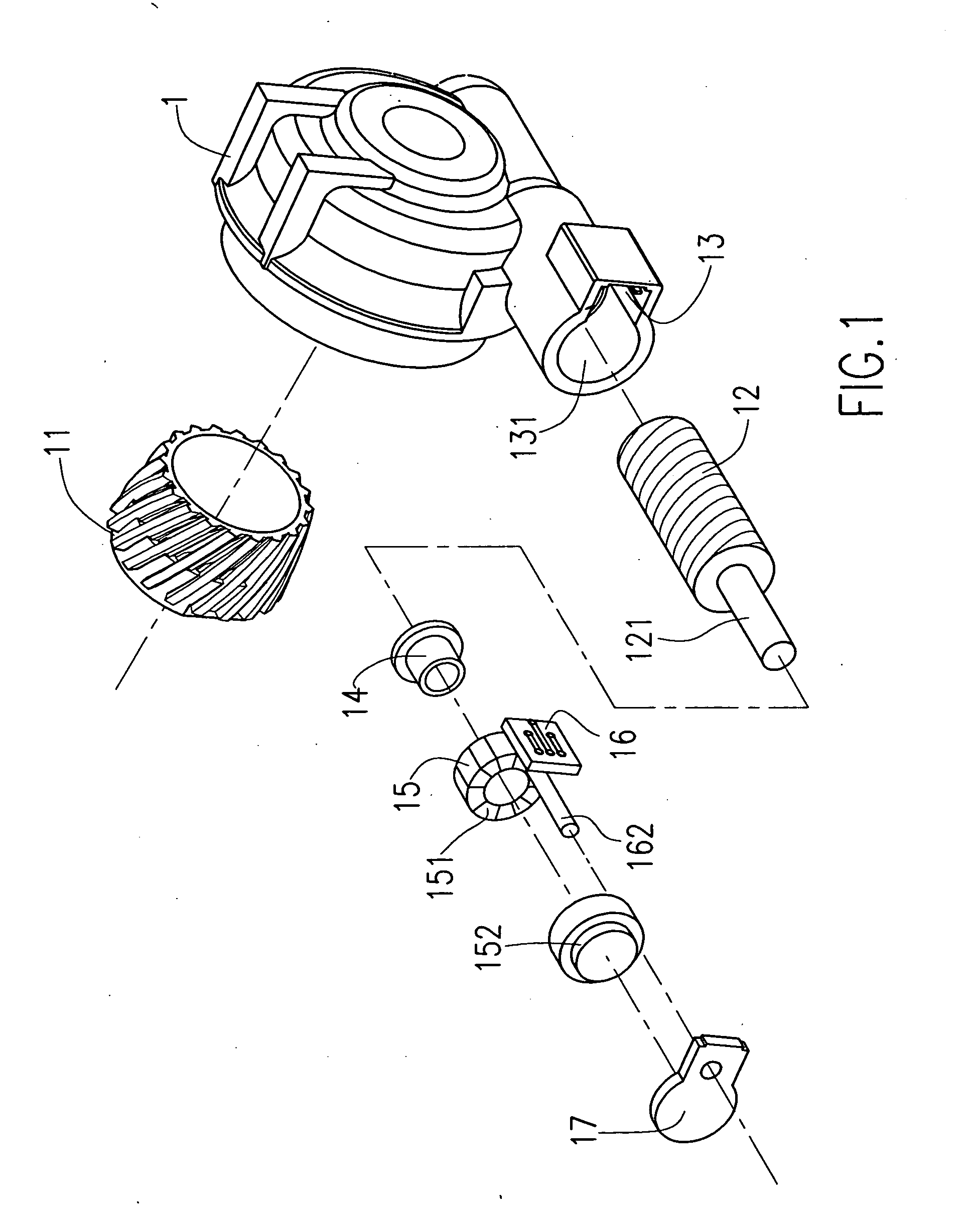
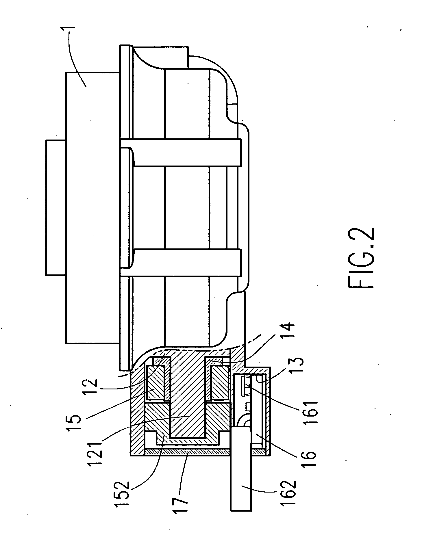
[0017] Referring to FIGS. 1˜3, a driven gear 11 and an output gear 12 are meshed together in a gearbox 1, which is connectable to the front fork of a motorcycle. An annular magnetic device 15 having radially arranged magnetic zones 151 is receiving chambered on the gear shaft 121 of the output gear 12 for synchronous rotation with the output gear 12. A circuit board 16 is fixedly receiving chambered in a receiving chamber 13 inside the gearbox 1 corresponding to the annular magnetic device 15. The circuit board 16 comprises a sensor 161 facing the periphery of the annular magnetic device 15. The sensor 161 can be a Hall IC or solenoid switch. During running of the motorcycle, the driven gear 11 is driven to rotate the output gear 12 and the annular magnetic device 15, thereby causing the sensor 161 to be induced by the magnetic zones 151 of the annular magnetic device 15 to output to an output signal indicative of the speed of rotation of the annular magnetic device 15 to an electro...


PUM


Abstract

A speedometer gear output structure includes a gearbox installed in a motorcycle and holding a driven gear and an output gear for synchronous rotation with the wheels of the motorcycle, an annular magnetic device fastened to the gear shaft of the output gear for synchronous rotation, and a circuit board mounted in the gearbox and holding a sensor corresponding to peripheral magnetic zones of the annular magnetic device for outputting an output signal indicative of the speed of rotation of the output gear.

Description

BACKGROUND OF THE INVENTION [0001] 1. Field of the Invention [0002] The present invention relates to a speedometer for motor vehicle and, more particularly, to a speedometer gear output structure. [0003] 2. Description of the Related Art [0004] In a conventional mechanical speedometer driving structure as shown in FIG. 1, the axle 41 of the wheel hub 4 has two lugs 43 axially extended from the end 42, a gearbox 3 is fastened to the front fork of the motorcycle to hold a driven gear 31, and a driving member 33 is coupled to the driven gear 31, and an output gear 32 meshed with the driven gear 31 and coupled to a speedometer cable 34. The driven gear 31 has two opposite flat engagement portions 311 on the periphery. The driving member 33 has two flat engagement portions 331 bilaterally disposed on the inside and respectively engaged with the flat engagement portions 311, and two peripheral lugs 332 outward extended from the periphery at two sides in reversed directions. During rotatio...

Claims


Application Information

Patent Timeline
IPC IPC(8): G01P3/42
CPCG01P3/487G01P1/04
Inventor SU, KUO-HSINHUANG, PAULCHEN, PAUL FEI-TA
Owner SU KUO HSIN
Why Eureka
Try Eureka