Multifunction sensor system and method for supervising room conditions

a multi-functional sensor and room condition technology, applied in chemical methods analysis, instruments, material analysis, etc., can solve the problems of increasing the overall energy consumption of the sensor system, the inability to integrate the sensors for occupancy, temperature, humidity and cosub>2 /sub>concentration in one single wireless sensor device that measures these parameters, and the low installation cost justify the extra expenses of the wireless sensor. , to achieve the effect of reducing the thickness of the whole ultrasonic transducer uni

Inactive Publication Date: 2012-05-03
KONINKLIJKE PHILIPS ELECTRONICS NV
View PDF4 Cites 7 Cited by
  • Summary
  • Abstract
  • Description
  • Claims
  • Application Information

AI Technical Summary

Benefits of technology

[0010]Using an ultrasonic transducer for the above purpose makes it possible to do without an extra CO2 sensor, lowering the constructional effort and the overall construction costs of the multifunction sensor system as well as its energy consumption, making it possible to construct a system which runs completely wireless. Consequently, the installation of a multifunction sensor system according to the present invention is easy and inexpensive. Ultrasonic transducers are commonly known for detecting the room occupancy, their integration in the inventive sensor system and the use of run-time effects of the emitted ultrasonic waves for indirectly deriving the CO2 concentration provides a very effective general concept.
[0015]According to a different embodiment, the ultrasonic wave guide has the form of a bended horn. The bending parameter is correctly chosen so that no signal degradation will be introduced, and as such the thickness of the whole ultrasonic transducer unit can be decreased.

Problems solved by technology

The lower installation costs justify the extra expenses of the wireless sensors.
In commonly known systems, these different parameters have to be measured by a multifunction sensor system comprising a sensor for each parameter, increasing the overall energy consumption of the sensor system.
Sensors for occupancy, temperature, humidity and CO2 concentration are hard to integrate in one single wireless sensor device that measures these parameters.
The power requirements of the such a system with one sensor for each parameter are high and shorten the lifetime for the multifunction sensor system when it is run on an independent energy supply like a battery.
The high energy consumption also causes problems in employing independent energy harvesting methods like solar cells or the like.

Method used


Image

  • Multifunction sensor system and method for supervising room conditions
  • Multifunction sensor system and method for supervising room conditions
  • Multifunction sensor system and method for supervising room conditions

Examples


Embodiment Construction

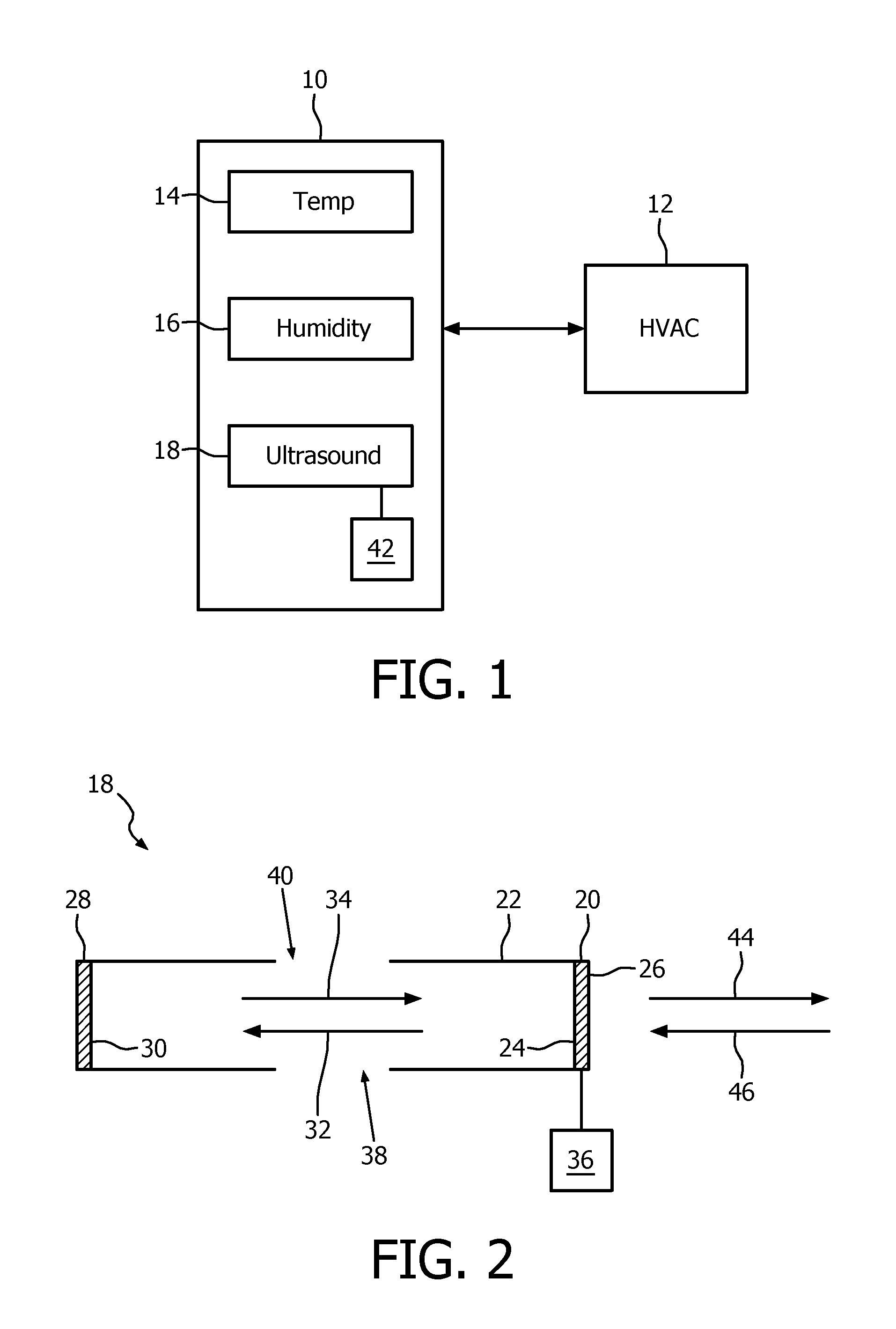
[0036]The building management system as shown in FIG. 1 comprises a multifunction sensor system generally marked by reference number 10, and a control system on the right side of the figure marked by reference number 12. The multifunction sensor system 10 is provided for supervising the conditions of a room of a building which is to be controlled by the building management system. For this purpose different parameters concerning the state of the room are measured and derived by the multifunction sensor system 10 and transmitted wirelessly to the control system 12. The control system 12 can comprise a heating air conditioning and ventilation (HVAC) system for managing the atmospherical conditions of the room in question, i.e., temperature, humidity and so on. For example, the present atmospherical conditions and the occupancy state of the room is measured, and the measured data are transmitted wirelessly from the multifunction sensor system 10 to the control system 12, which in turn ...


PUM


Abstract

The invention refers to a multifunction sensor system and a corresponding method for supervising room conditions, comprising a temperature sensor, a humidity sensor, an ultrasonic transducer for emitting ultrasonic waves and being positioned in a fixed distance to a reflecting fixed reflective surface. For calculating the CO2 concentration in the supervised room, the time of flight of ultrasonic waves between the transducer and the fixed reflective surface is measured, and the CO2 concentration is calculated from the output values of the temperature sensor, the humidity sensor and the measured time of flight.

Description

FIELD OF THE INVENTION[0001]The present invention relates to a multifunction sensor system and a corresponding method for supervising room conditions, especially in a building management system for controlling atmospherical room conditions.BACKGROUND OF THE INVENTION[0002]Building management systems require information about the conditions of the rooms of the building, for example, the room occupancy, room temperature, humidity and CO2 concentration. On the basis of this information, a control of the atmospherical room conditions can be carried out by a heating air conditioning and ventilation (HVAC) system.[0003]The necessary information is derived from measuring values which are provided by different kinds of sensors which are arranged in the respective rooms to be controlled. In common systems, each sensor is provided according to the parameter to be measured, for example, a temperature sensor for providing a present temperature value, a humidity sensor for measuring humidity, an...

Claims


Application Information

Patent Timeline
Patent Type & Authority Applications(United States)
IPC IPC(8): G06F19/00
CPCG01N29/024G01N29/2481G01N2291/021G01N2291/045H05B37/0218H05B37/0227Y02B20/46H05B47/11H05B47/105Y02B20/40H05B47/115G01N29/24G01V1/00
Inventor PASVEER, WILLEM F.DIRKSEN, PETERSREEDHARAN NAIR, BIJU K.
Owner KONINKLIJKE PHILIPS ELECTRONICS NV
Why Eureka
Try Eureka