
Physical security system for wireless access points that prevents removal of the access point and associated connectors

a security system and wireless access technology, applied in the direction of live contact access prevention, electrical equipment, coupling device connection, etc., can solve the problems of security system not hiding branding and esthetic design, and achieve the effect of eliminating thermal degradation and easy and inexpensive installation

Inactive Publication Date: 2006-12-12
CISCO TECH INC
View PDF2 Cites 7 Cited by
  • Summary
  • Abstract
  • Description
  • Claims
  • Application Information

AI Technical Summary

Benefits of technology

[0009]Advantages of the security system, include, but are not limited to, easy and inexpensive installation, elimination of thermal degradation of the access point, does not compromise the ventilation of the access point enclosure, does not compromise the access point's electrical and regulatory aspects, and allows the visibility of all the access point's visual indicators.

Problems solved by technology

Additionally, the security system does not hide the branding and esthetic design of the access point enclosure.

Method used


Image

  • Physical security system for wireless access points that prevents removal of the access point and associated connectors
  • Physical security system for wireless access points that prevents removal of the access point and associated connectors
  • Physical security system for wireless access points that prevents removal of the access point and associated connectors

Examples


Embodiment Construction

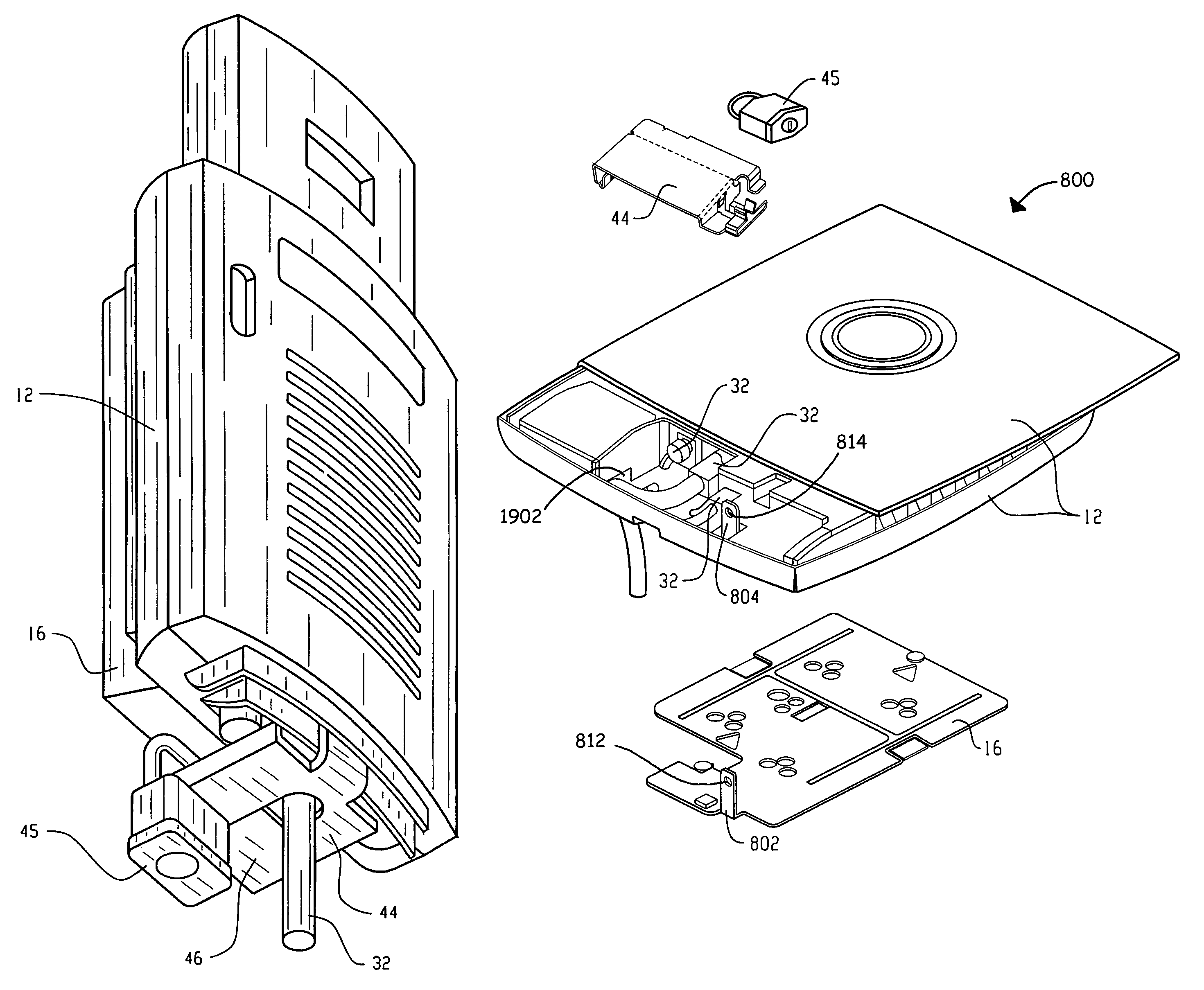
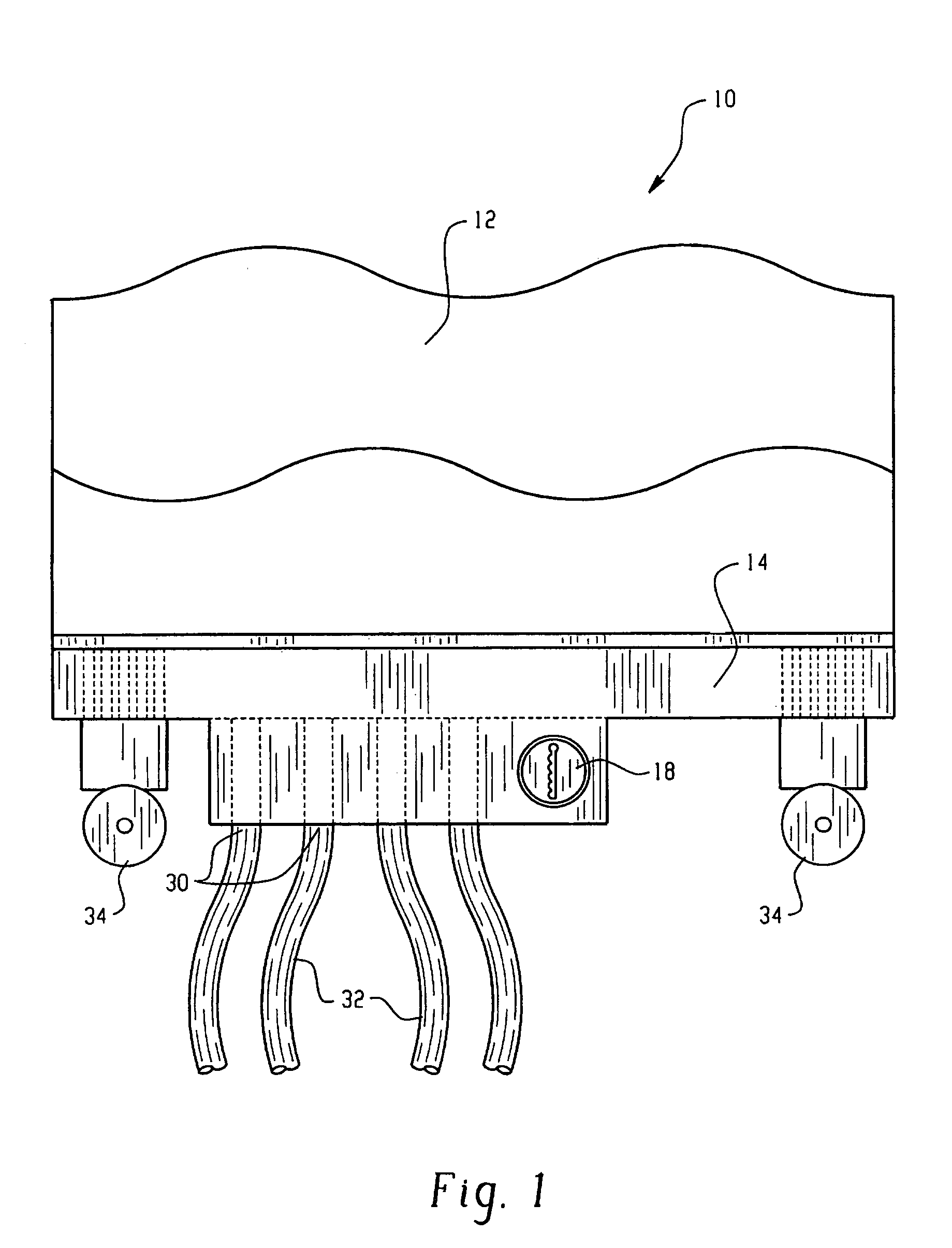
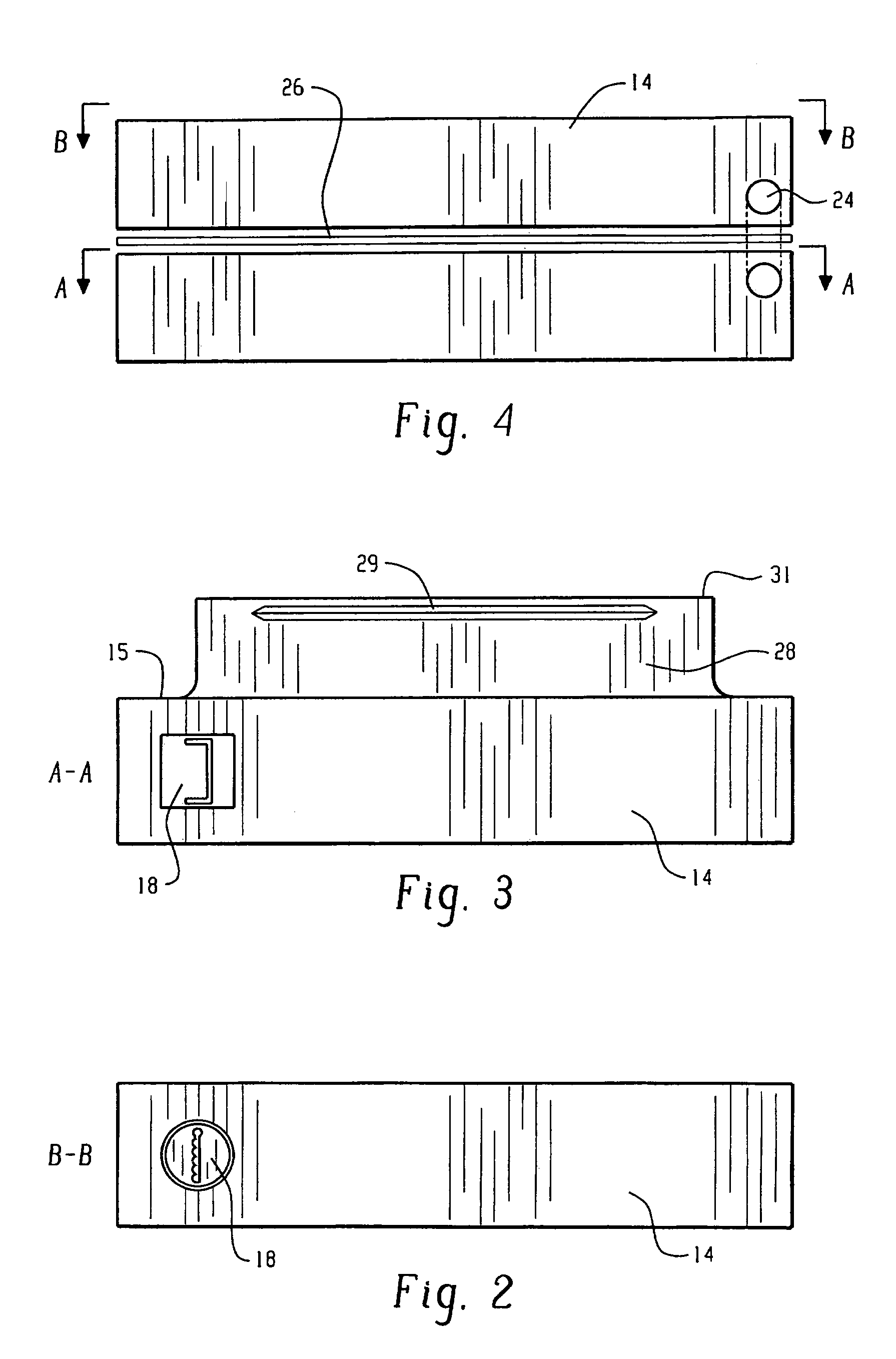
[0030]The present invention is directed to a physical security system for wireless access points. FIG. 1 shows a preferred embodiment of the system according to the present invention, generally designated 10. The system 10 comprises a clamp assembly 14 and a locking device 18 which are secured to an access point, to prevent theft of the access point and to prevent removal or access of the I / O panel connectors 32 and antennas 34 of the access point.

[0031]The clamp assembly 14 is designed to clamp around various I / O panel connectors, such as Ethernet connectors 32, fiber connectors 32, console port connectors 32, and / or antennas 34 connected to the access point. The clamp assembly 14 also securably attaches to a portion of the access point. This prevents removal of the access point, and physically blocks any unauthorized user from accessing the I / O ports.

[0032]In a preferred embodiment, a framing 12 encloses the access point protecting it from damage. The clamp assembly 14 is then sec...


PUM


Abstract

This invention is directed to a security system for wireless access points which includes a mounting bracket, an enclosure frame, a lock plate and a locking device. The mounting bracket couples the access point to a stationary surface. The enclosure frame is adapted to be fastened to the mounting bracket and configured to cover the mounting bracket. The lock plate is suitably adapted to secure the enclosure frame to the mounting bracket and to prevent access to either an I / O connector and / or a power connector. The locking device secures the lock plate to the mounting bracket and enclosure frame. When engaged by the locking device, the lock plate prevents removal of the access point and access to either the I / O connector and / or the power connector.

Description

[0001]This application is a continuation-in-part of U.S. patent application Ser. No. 10 / 266,377 filed Oct. 8, 2002, which is hereby incorporated by reference.BACKGROUND OF THE INVENTION [0002]This invention is directed to physical security systems for wireless access points. More particularly, this invention is directed to a physical security system for wireless access points which is comprised of a clamp assembly and a locking device.[0003]Users of wireless access points are concerned about the physical security of distributed access points throughout their facilities. These security concerns include theft of the access points and hacking into the user's network via unauthorized access to the access point's I / O panel connectors, such as the Ethernet, fiber and / or console port connectors.[0004]To address these security problems, access point users are placing the access points in metal security boxes to secure the access points. However, this solution results in other problems, such...

Claims


Application Information

Patent Timeline
Patent Type & Authority Patents(United States)
IPC IPC(8): H01R13/44H01R13/639
CPCH01R13/6397
Inventor LINDNER, LEONARD S.
Owner CISCO TECH INC
Learn More