Light-emitting diode display device and light-emission control method thereof

a technology of light-emitting diodes and display devices, which is applied in semiconductor devices, electrical devices, instruments, etc., can solve the problems of uneven display brightness and/or image flicker, user may see broken or torn images, and may not be able to solve the problem of delayed display images, etc., to reduce the occurrence of flicker of displayed images and improve display quality.

Active Publication Date: 2022-08-02
AU OPTRONICS CORP
View PDF1 Cites 0 Cited by
  • Summary
  • Abstract
  • Description
  • Claims
  • Application Information

AI Technical Summary

Benefits of technology

[0005]The disclosure also provides a light-emitting diode display device capable of reducing image flicker while maintaining luminous efficacy.
[0009]Based on the above, the present disclosure configures each light-emission signal to generate periodically multiple pulses based on a set period during a light-emitting time period amid two adjacent frame periods, thereby driving each corresponding display row to emit light according to the corresponding write-in data. This way, when the frame rate is varied dynamically, the display image does not flicker nor be torn due to the varied frame rate, and improves the display quality effectively. In addition, in the embodiments of the disclosure, the operating rate of the ramp control signal and the light-emission signal is higher than the operating rate of the first gate drive signal on which the data writing operation is based, so as to reduce the occurrence of flicker of the displayed images.

Problems solved by technology

In the conventional display device, when some applications (such as gaming programs) are executed, since the number of game frames that are output based on the display card is not in sync with the scanning rate of the display device, the user may see broken or torn images.
However, after the function of vertical synchronization is turned on, since the display device still maintains a fixed rate of operation, the problem of delayed display images is still likely to occur.
Nevertheless, regardless of the synchronization technologies, the synchronization still relies on reducing the frame rate of the display device.
And such method still has the issue(s) of uneven display brightness and / or image flicker when a pulse-driven light-emitting diode display device varies its refresh rate.

Method used


Image

  • Light-emitting diode display device and light-emission control method thereof
  • Light-emitting diode display device and light-emission control method thereof
  • Light-emitting diode display device and light-emission control method thereof

Examples


Embodiment Construction

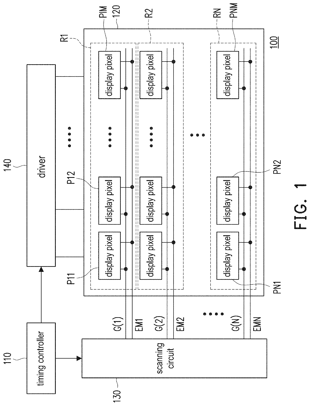
[0020]FIG. 1 is a schematic view of a light-emitting diode display device according to an embodiment of the present disclosure. A display device 100 includes a timing controller 110, a pixel array 120, a scanning circuit 130, and a driver 140. The pixel array 120 is composed of a plurality of display pixels P11 to PNM. The display pixels P11 to PNM form a plurality of display rows R1 to RN. The scanning circuit 130 is coupled to the timing controller 110 and the display rows R1 to RN. The scanning circuit 130 may generate a plurality of scan signals G(1) to G(N) and a plurality of light-emission signals EM1 to EMN according to a timing control command TCMD sent by the timing controller 110. The scan signals G(1) to G(N) and the light-emission signals EM1 to EMN are respectively provided to the display rows R1 to RN, and are respectively adapted to drive the display pixels P11 to PNM in the display rows R1 to RN.

[0021]The timing controller 110 is further coupled to the driver 140. Th...


PUM

PropertyMeasurementUnit
timeaaaaaaaaaa
delay timeaaaaaaaaaa
timeaaaaaaaaaa

Abstract

A light-emitting diode display device and a light-emission control method thereof are provided. The light-emitting diode display device includes a timing controller, multiple display pixels, and a scanning circuit. The display pixels form multiple display rows. The scanning circuit generates multiple scan signals and multiple light-emission signals that respectively drive the display rows. During a first data-writing time period of a first frame period, the timing controller provides multiple writing data to be respectively written into the display rows. During a light-emitting time period, the scanning circuit drives each of the light-emission signals to generate multiple pulses periodically according to a set period to drive the corresponding display rows. The light-emitting time period is after the first data-writing time period and before a second data-writing time period of a second frame period ends.

Description

CROSS-REFERENCE TO RELATED APPLICATION[0001]This application claims the priority benefits of Taiwan application serial no. 109128810, filed on Aug. 24, 2020, and Taiwan application serial no. 109145728, filed on Dec. 23, 2020. The entirety of each of the above-mentioned patent applications is hereby incorporated by reference herein and made a part of this specification.BACKGROUNDTechnical Field[0002]The disclosure relates to a light-emitting diode display device and a light-emission control method thereof, and particularly to a light-emitting diode display device applicable to the variation of frame rate and a light-emission control method thereof.Description of Related Art[0003]In the conventional display device, when some applications (such as gaming programs) are executed, since the number of game frames that are output based on the display card is not in sync with the scanning rate of the display device, the user may see broken or torn images. To solve this issue, vertical synch...

Claims


Application Information

Patent Timeline
Patent Type & Authority Patents(United States)
IPC IPC(8): G09G3/32H01L27/15
CPCG09G3/32H01L27/156G09G2310/0267G09G2310/0275G09G2310/08G09G2320/0233G09G2320/02G09G2300/0819G09G2300/0842G09G2300/0861G09G2300/0876G09G2310/066
Inventor KUO, YU-CHIEHCHIU, YU-HSUNLIU, KAI-HSIANGCHANG, CHE-CHIAWU, SHANG-JIELI, MEI-YIXI, PENG-BOCHIANG, CHIN ICHEN, YAN-RUGUO, TING-WEIHSIEH, CHIA-TING
Owner AU OPTRONICS CORP
Why Eureka
Try Eureka