
Display apparatus and driving method therefor

a technology of display apparatus and driving method, applied in the field of display technologies, can solve the problems of image flicker, image flicker, and attenuation of the working voltage of the related componen

Active Publication Date: 2020-01-09
HKC CORP LTD +1
View PDF5 Cites 0 Cited by
  • Summary
  • Abstract
  • Description
  • Claims
  • Application Information

AI Technical Summary

Benefits of technology

This patent aims to provide a display apparatus and a driving method that can alleviate image flicker issues by adjusting the common voltage. The method can maintain the desired voltage value and ensure a stable relationship with the Gamma reference voltage, even after extended usage. Additionally, the display apparatus can adaptively regulate the common voltage, making it applicable to various display devices and electronic products. Overall, this invention allows for improved image quality and stability of display apparatuses while maintaining manufacturing requirements and cost-effectiveness.

Problems solved by technology

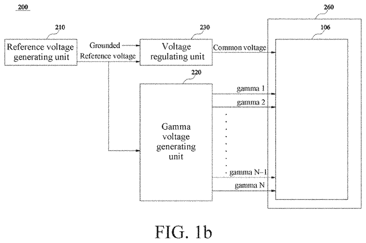
However, when the common voltage VCOM and the Gamma reference voltage Gamma are unsymmetrical in numeric relationship, image flicker occurs.
(1) Sampling is performed on a panel after the panel is produced. An optimum common voltage VCOM_Y of the sampled panel is obtained through debugging, and then it is considered that an optimum common voltage VCOM of another display panel is the same as the optimum common voltage VCOM_Y of the sampled panel. A disadvantage of this solution is that, due to unstable manufacturing of a display panel in a manufacturing process, different display panels are different in manufacturing, leading to a difference between optimum common voltages VCOM of the different panels. Because the different display panels have different optimum common voltages VCOM, the optimum common voltages VCOM_Y are not definitely optimum. This causes image flicker.
(2) An optical sensor is added to a production line to detect image flicker strength and software is used to debug an optimum common voltage VCOM of each display panel. A common voltage VCOM occurring when the image flicker strength is the weakest is regarded as an optimum common voltage VCOM_Y of the display panel. A disadvantage of this solution is time-consuming and is not applicable to a product in which a printed circuit board (X board) is separated from a control board (C board). This is because the printed circuit board (X board) and the control board of this product are usually separately delivered, causing an error of an optimum VCOM when the panel is delivered to a client.
Further, working voltages of related components attenuate as use time increases.
In addition, because attenuation speeds of voltage signals of the common voltage VCOM, the Gamma reference voltage Gamma and the like are inconsistent, after the display panel is used for a long time, the common voltage VCOM gradually deviates from an optimum voltage value.
This causes problems such as flicker.

Method used


Image

  • Display apparatus and driving method therefor
  • Display apparatus and driving method therefor
  • Display apparatus and driving method therefor

Examples


Embodiment Construction

[0029]The following embodiments are described with reference to the accompanying drawings, which are used to exemplify specific embodiments for implementation of this application. Terms about directions mentioned in this application, such as “on”, “below”, “front”, “back”, “left”, “right”, “in”, “out”, and “side surface” merely refer to directions in the accompanying drawings. Therefore, the terms used about directions are used to describe and understand this application, and are not intended to limit this application.

[0030]The accompanying drawings and the description are considered to be essentially exemplary, rather than limitative. In the figures, modules with similar structures are represented by using the same reference number. In addition, for understanding and ease of description, the size and the thickness of each component shown in the accompanying drawings are arbitrarily shown, but this application is not limited thereto.

[0031]In the accompanying drawings, for clarity, t...


PUM


Abstract

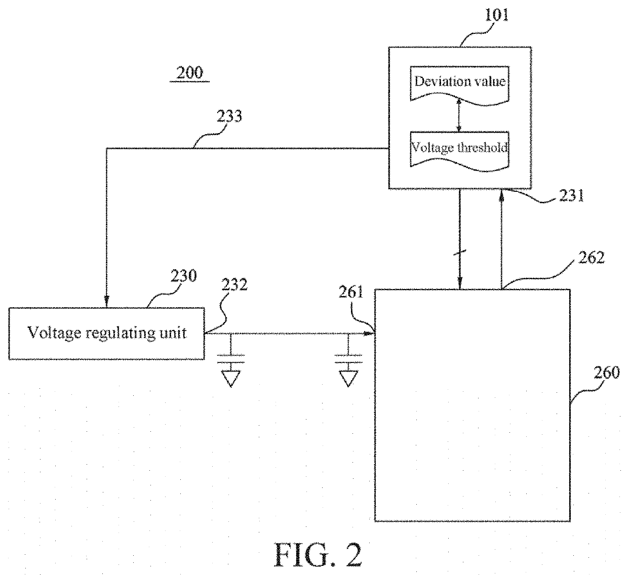
This application provides a display apparatus and a driving method therefor. The display apparatus includes: a display panel, including a first input line and a first output line, where the first input line obtains a common voltage, and the first output line outputs a common feedback voltage; a voltage regulating unit, including a second output line, where the second output line outputs the common voltage; and a timing controller, including a control line and a second input line, where the control line outputs a voltage regulating signal, and the second input line obtains the common feedback voltage, where the timing controller continuously obtains the common feedback voltage, and selects, from common feedback voltage values, several voltage values as a regulation condition, and outputs the voltage regulating signal according to the regulation condition, where the voltage regulating unit regulates the common voltage according to the voltage regulating signal.

Description

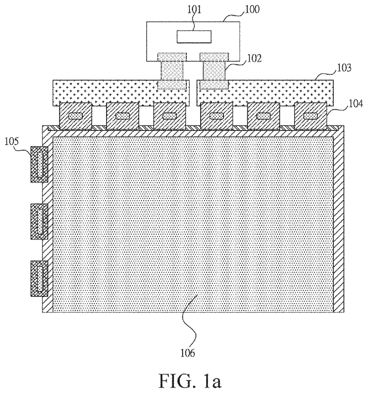
BACKGROUNDTechnical Field[0001]This application relates to the field of display technologies, and in particular, to a display apparatus and a driving method therefor.Related Art[0002]In a display, a system board is connected to a control board (C-Board) by using a line, the control board is connected to a printed circuit board (PCB) by using, for example, a flexible flat cable (FFC), and the printed circuit board is then connected to a display area by using a source-chip on film (S-COF) and a gate-chip on film (G-COF). A driving manner of the display includes: The system board transmits a color (for example, R / G / B) compression signal, a control signal, and power to the control board. The signals are transmitted to a source circuit and a gate circuit of the printed circuit board after being processed by a timing controller (TCON) on the control board. Necessary data and power are transmitted to the display area by using the source-chip on film and the gate-chip on film, so that the d...

Claims


Application Information

Patent Timeline
IPC IPC(8): G09G3/20
CPCG09G3/20G09G2310/08G09G3/3655G09G3/3696G09G2310/027G09G2320/0247G09G2320/0673G09G2330/021G09G2330/028
Inventor ZHAO, WENQIN
Owner HKC CORP LTD
Learn More