
Flicker control circuits for liquid crystal devices

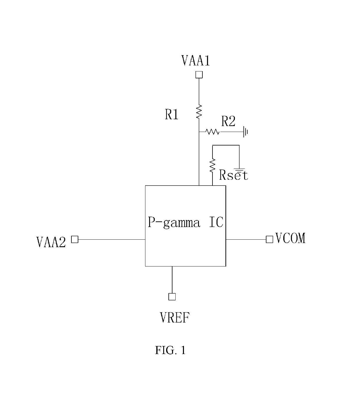
a control circuit and liquid crystal technology, applied in the direction of electric variable regulation, process and machine control, instruments, etc., can solve the problems of component error, worse flicker, and error due to component errors, so as to reduce image flicker of lcd, enhance common voltage precision, and increase the precision of dividing reference voltage.

Inactive Publication Date: 2019-06-11
TCL CHINA STAR OPTOELECTRONICS TECH CO LTD
View PDF2 Cites 0 Cited by
  • Summary
  • Abstract
  • Description
  • Claims
  • Application Information

AI Technical Summary

Benefits of technology

A flicker control circuit for LCDs is proposed to improve their display performance by reducing image flicker. The circuit achieves this by changing the partial voltage of the common voltage, which is affected by a dividing reference voltage. This enhances the precision of the common voltage, and by allowing it to change in the same direction as the dividing reference voltage, image flicker can be reduced.

Problems solved by technology

Under such circumstances, errors may exist due to the errors caused by the components, such as resistors or integrated chips (ICs), within the CB, the external operational voltages, and the difference between the reference voltages and the common voltage.
The above errors, such as the operational voltage and the difference between the reference voltage and the common voltage, may cause flicker.
The flicker may be worse when the voltage is asymmetrical due to the inversed polarity.

Method used


Image

  • Flicker control circuits for liquid crystal devices
  • Flicker control circuits for liquid crystal devices
  • Flicker control circuits for liquid crystal devices

Examples


Embodiment Construction

[0026]Various example embodiments will now be described more fully with reference to the accompanying drawings in which some example embodiments are shown. In the drawings, the thicknesses of layers and regions may be exaggerated for clarity. In the following description, in order to avoid the known structure and / or function unnecessary detailed description of the concept of the invention result in confusion, well-known structures may be omitted and / or functions described in unnecessary detail.

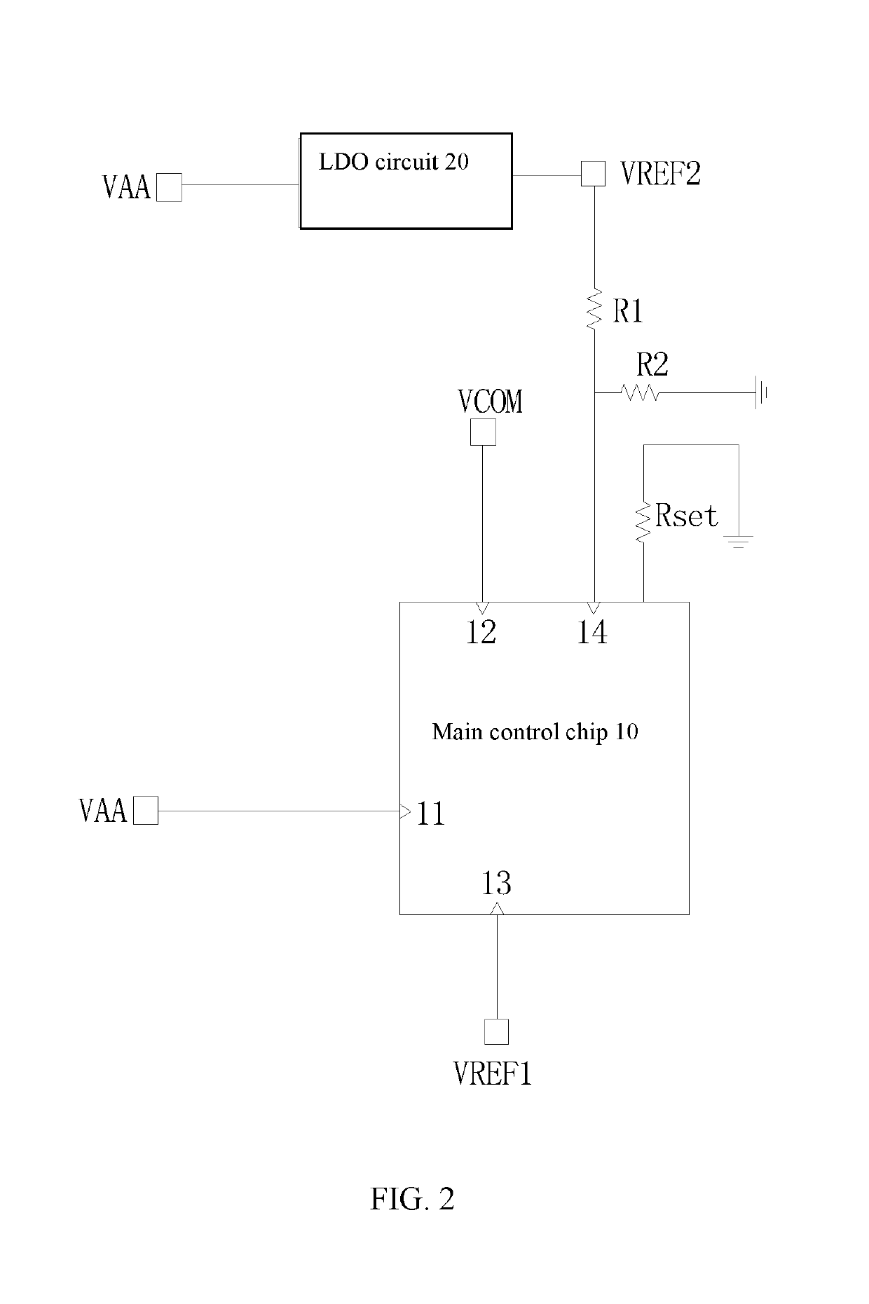
[0027]FIG. 2 is a circuit diagram of the flicker control circuit of LCDs in accordance with one embodiment.

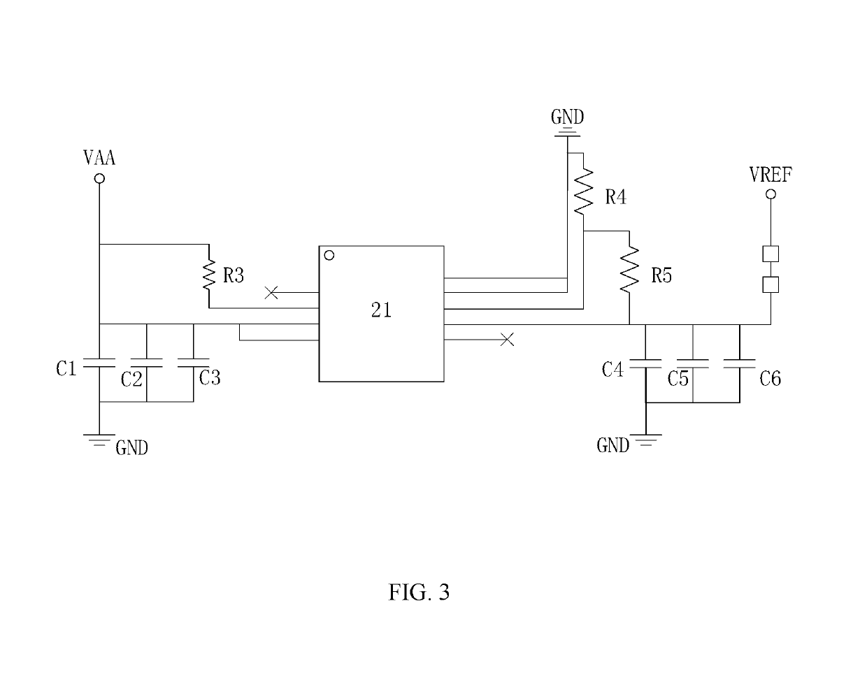
[0028]Referring to FIG. 2, the flicker control circuit includes a main control chip 10, a low differential voltage regulator (LDO) circuit 20, a first resistor (R1) connected to the main control chip 10, a second resistor (R2) connected to the main control chip 10, and a reset resistor (Rset). The main control chip 10 includes an operational voltage input end 11 for receiving an operation...


PUM


Abstract

A flicker control circuit of liquid crystal devices (LCDs) includes a main control chip, a low differential voltage regulator (LDO) circuit, a first resistor, a second resistor, and a reset resistor. The main control chip includes an operational voltage input end, a common voltage output end, and a dividing reference voltage input end. The LDO circuit receives a voltage provided by an external power module and generates a dividing reference voltage in accordance with the received voltage. One end of the first resistor connects to the LDO circuit to receive the dividing reference voltage, and the other end of the first resistor connects to the dividing reference voltage input end. The flicker of the LCDs may be reduced such that the display performance of the LCDs may be enhanced.

Description

BACKGROUND OF THE INVENTION1. Field of the Invention[0001]The present disclosure relates to liquid crystal display technology, and more particularly to a flicker control circuit of liquid crystal devices (LCDs).2. Discussion of the Related Art[0002]Currently, liquid crystal panels and control boards (CBs) may be separately shipped out in some business models. Under such circumstances, errors may exist due to the errors caused by the components, such as resistors or integrated chips (ICs), within the CB, the external operational voltages, and the difference between the reference voltages and the common voltage. Thus, the optical common voltage of a variety of CBs may be different for one liquid crystal panel. During the mass production, the auto gamma process is applied to various CBs to obtain the corresponding parameters for achieving the optical flicker control. The parameters are saved within the Flash memory with the liquid crystal panel. However, different CBs may be adopted ra...

Claims


Application Information

Patent Timeline
Patent Type & Authority Patents(United States)
IPC IPC(8): G09G3/36G05F3/08
CPCG09G3/3696G05F3/08G09G2330/02G09G2320/0247
Inventor LI, WENFANGZHANG, XIANMINGCHEN, XINHONG
Owner TCL CHINA STAR OPTOELECTRONICS TECH CO LTD
Learn More