
Method and system for mitigating image flicker from strobed lighting systems

a technology of strobe lighting and image flicker, which is applied in the direction of color television details, television systems, vehicle components, etc., can solve the problems of high frequency of pulses, inability to see the light emitter, and inability to process image frames in this way to identify and remove flicker caused by light emitters

Pending Publication Date: 2022-10-13
JAGUAR LAND ROVER LTD
View PDF0 Cites 0 Cited by
  • Summary
  • Abstract
  • Description
  • Claims
  • Application Information

AI Technical Summary

Benefits of technology

The patent text describes a system that can identify areas of image data that are likely to have flickering and apply image correction algorithms to those areas more efficiently. This results in faster and more effective image correction without needing to adjust the exposure time of the imaging device. This allows for better dynamic range and image quality in the first image data.

Problems solved by technology

The pulses are typically high frequency and thus not perceivable to a human observer.
If the camera frequency and light emitter frequency are not synchronised when a light emitter is captured in the scene, the lack of synchronisation can cause the light emitter to visibly appear flashing to an observer when the image data is reproduced, a problem which may be referred to as image flicker.
Processing image frames in this way to identify and remove flicker caused by the light emitter can be resource intensive.
Furthermore, by adjusting one or more exposure times of the camera to align with the light emitter frequency, the one or more adjusted exposure times are no longer configured to best capture the overall scene.
Therefore, dynamic range of the camera and thus image quality of the image data may be compromised.
Such an issue may be particularly prevalent for high dynamic range (HDR) cameras.

Method used


Image

  • Method and system for mitigating image flicker from strobed lighting systems
  • Method and system for mitigating image flicker from strobed lighting systems
  • Method and system for mitigating image flicker from strobed lighting systems

Examples


Embodiment Construction

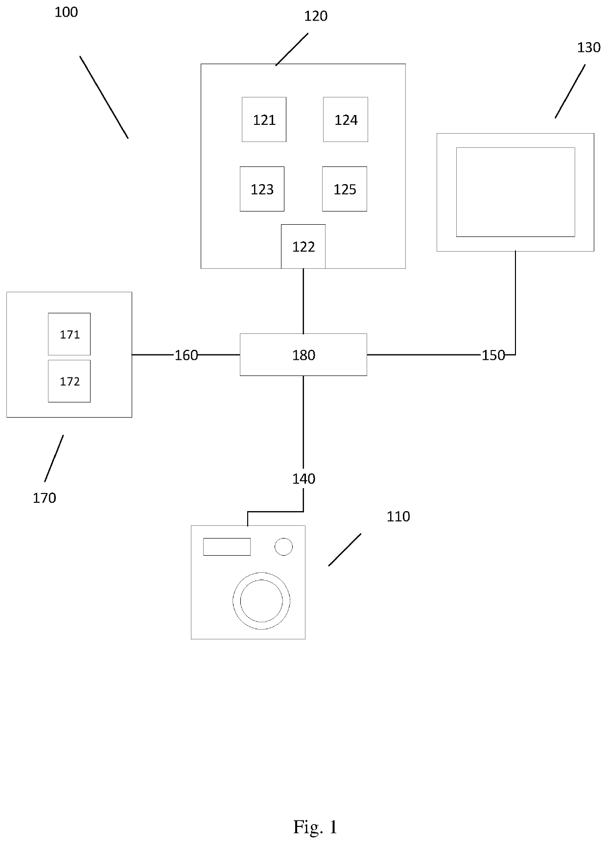
[0045]Embodiments of the present invention relate to the identification and mitigation of light emitter flicker for an imaging system. An imaging system 100 which may be configured to identify or mitigate light emitter flicker in accordance with various embodiments of the present invention is described herein with reference to the accompanying FIG. 1.

[0046]The imaging system 100 may be configured to generate image data 140 indicative of an environment. Embodiments of the present invention relate to the identification and mitigation of light emitter flicker in the image data 140 generated by the imaging system 100. According to some embodiments, the imaging system may be associated with a vehicle as will be explained, and the environment may comprise surroundings of the vehicle. For example, the environment may comprise surroundings within a line of sight of the vehicle. Embodiments of the present invention will be described with reference to the imaging system 100 being associated w...


PUM


Abstract

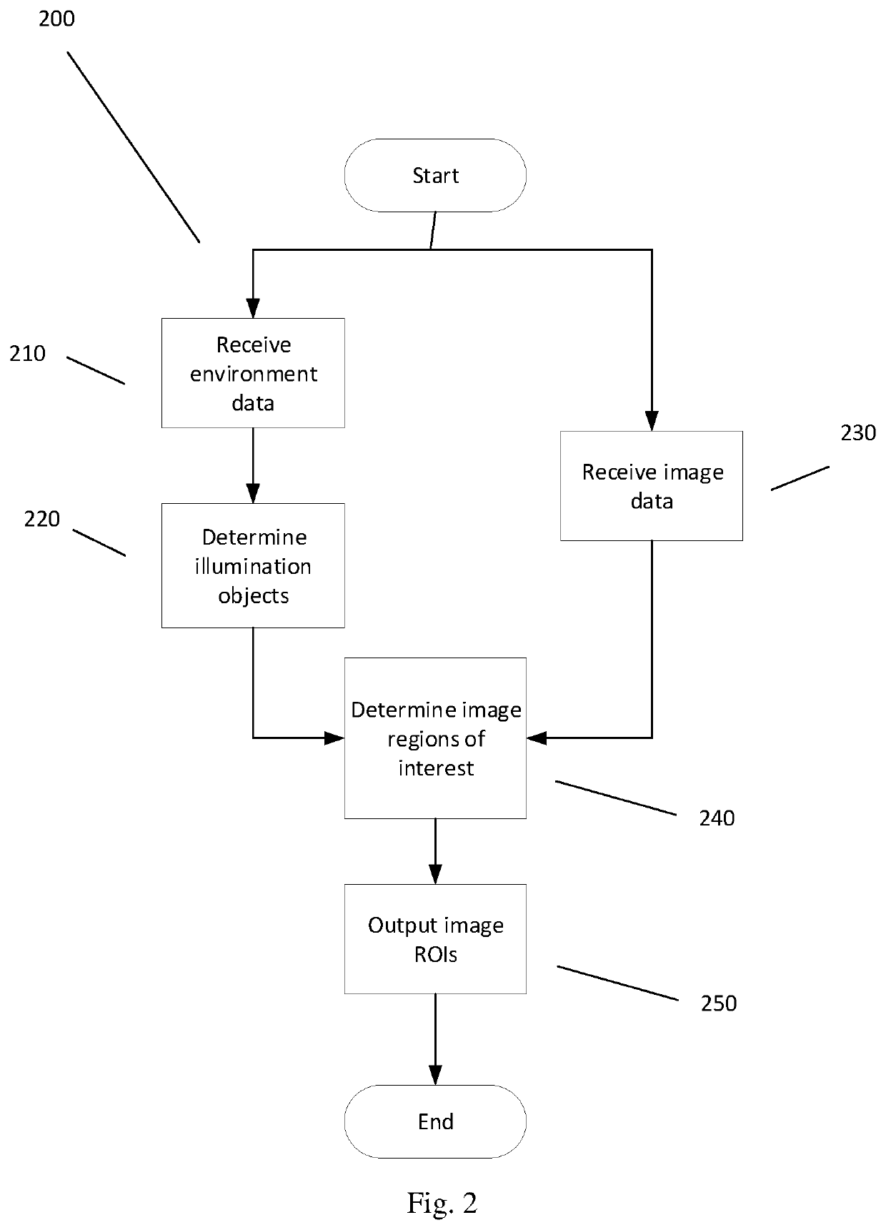
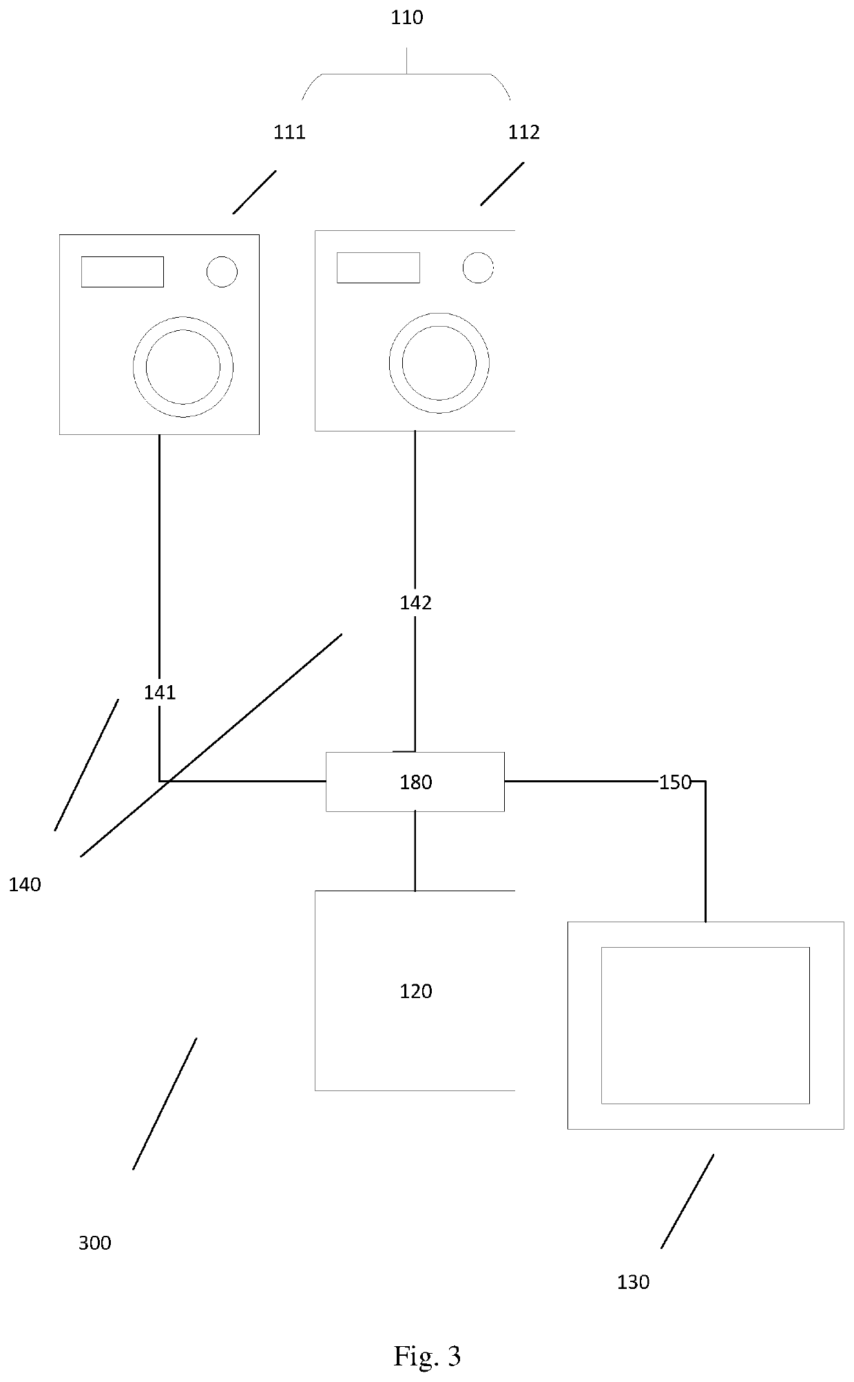
Aspects of the present invention relate to an image correction system (300) for mitigating image flicker from strobed lighting systems. The image correction system (300) comprises one or more controllers (120) comprising input means (122), processing means (121) and output means (122). The input means (122) is configured to receive, from a first imaging apparatus (111) comprising a first pixel array configured to operate with at least a first exposure time, first image data (141) indicative of an environment. The input means (122) are configured to receive, from a second imaging apparatus (112) comprising a second pixel array configured to operate with at least a second exposure time different to the first exposure time, second image data (142) indicative of at least a portion of the environment. The processing means (121) are configured to identify strobed lighting regions of the first image data (141) and strobed lighting regions of the second image data (142); and to determine corrected image data for mitigating image flicker of the strobed lighting regions of the first image data (141) in dependence on a correspondence between the strobed lighting regions of the first image data (141) and the strobed lighting regions of the second image data (142). The output means (122) is configured to output a signal indicative of the corrected image data.

Description

TECHNICAL FIELD[0001]The present disclosure relates to mitigating image flicker from strobed lighting systems. Aspects of the invention relate to a controller, a system, a vehicle, a method and a computer-readable medium comprising computer readable instructions.BACKGROUND[0002]It is known to provide image processing techniques to mitigate light emitter flicker in image data. Light emitters, for example LEDs, are controlled to emit light in a series of pulses. The pulses are typically high frequency and thus not perceivable to a human observer. When a camera captures image data of a scene, the image data comprises a series of frames each exposed for an exposure time at short intervals, for example at a frequency of 30 to 60 frames per second. If the camera frequency and light emitter frequency are not synchronised when a light emitter is captured in the scene, the lack of synchronisation can cause the light emitter to visibly appear flashing to an observer when the image data is rep...

Claims


Application Information

Patent Timeline
Patent Type & Authority Applications(United States)
IPC IPC(8): H04N5/235H04N5/247B60R1/12B60R1/26B60R11/04H04N23/90
CPCH04N5/2357H04N5/2353H04N5/247B60R1/12B60R1/26B60R11/04B60R2001/1215B60R2001/1253B60R2011/004H04N23/661H04N23/745H04N23/90B60R2300/105B60R2300/30B60R2300/8046H04N23/73
Inventor CLOSE, JOSHUAPRYKE, ALEXANDER
Owner JAGUAR LAND ROVER LTD
Learn More