Bone tie and bone tie inserter

a bone tie and inserter technology, applied in the field of bone tie and bone tie inserter, can solve the problems of affecting the repair of the facet, so as to facilitate the pivoting and/or rotating

Active Publication Date: 2022-10-04
SPINAL ELEMENTS INC
View PDF655 Cites 0 Cited by
  • Summary
  • Abstract
  • Description
  • Claims
  • Application Information

AI Technical Summary

Benefits of technology

[0012]In some embodiments, the bone tie advancer comprises a channel to receive the neck section of the bone tie. In some embodiments, the bone tie advancer comprises a curve. In some embodiments, the bone tie advancer comprises a rounded section to abut the rounded head of the bone tie. In some embodiments, the bone tie retriever comprises an opening, wherein the neck section pivots, or pivots and rotates, from extending from the channel to extending through the opening. In some embodiments, the bone tie retriever comprises one or more retention features configured to retain the bone tie. In some embodiments, the bone tie retriever comprises a ledge. In some embodiments, the ledge facilitates pivoting and / or rotating of the rounded head of the bone tie.

Problems solved by technology

Traumatic, inflammatory, and degenerative disorders of the spine can lead to severe pain and loss of mobility.
According to some studies, back and spinal musculoskeletal impairments are the leading causes of lost work productivity in the United States.
While many technological advances have focused on the spinal disc and artificial replacement or repair of the disc, little advancement in facet repair has been made.
This surgical procedure has a high rate of morbidity and can potentially lead to further clinical complications such as adjacent segment disorders.
This procedure is also not reversible.
Therefore, if the patient has an unsatisfactory result, they may be subject to additional surgical fusion procedures.

Method used


Image

  • Bone tie and bone tie inserter
  • Bone tie and bone tie inserter
  • Bone tie and bone tie inserter

Examples


Embodiment Construction

[0041]Although certain preferred embodiments and examples are disclosed below, it will be understood by those in the art that the disclosure extends beyond the specifically disclosed embodiments and / or uses of the invention and obvious modifications and equivalents thereof. Thus, it is intended that the scope should not be limited by the particular disclosed embodiments described below.

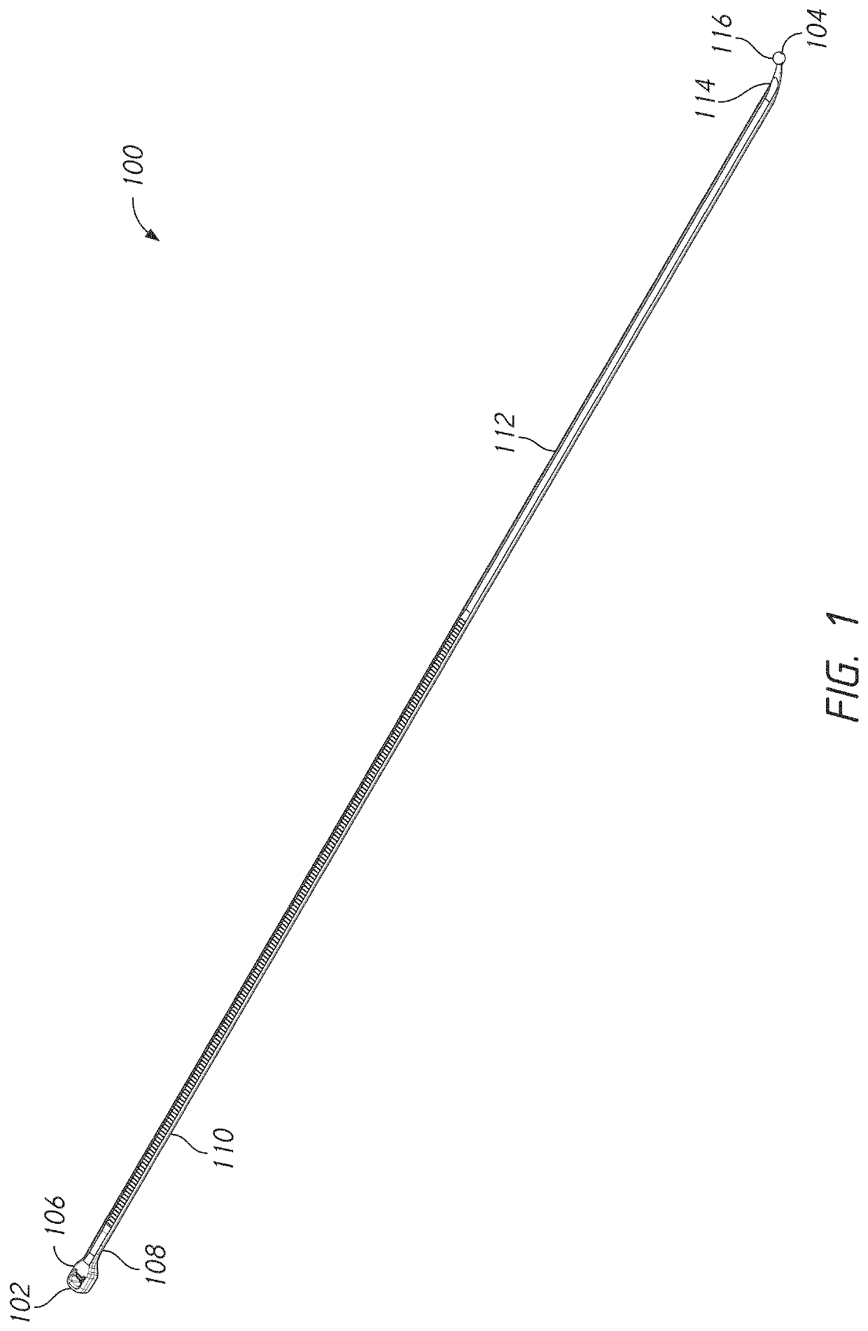
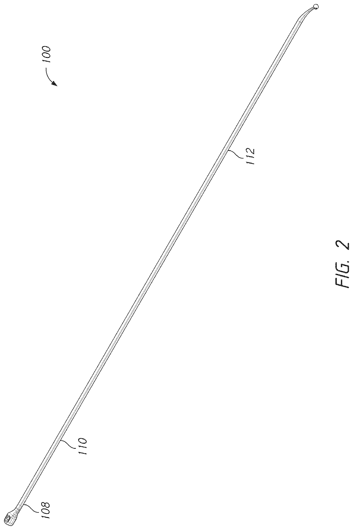
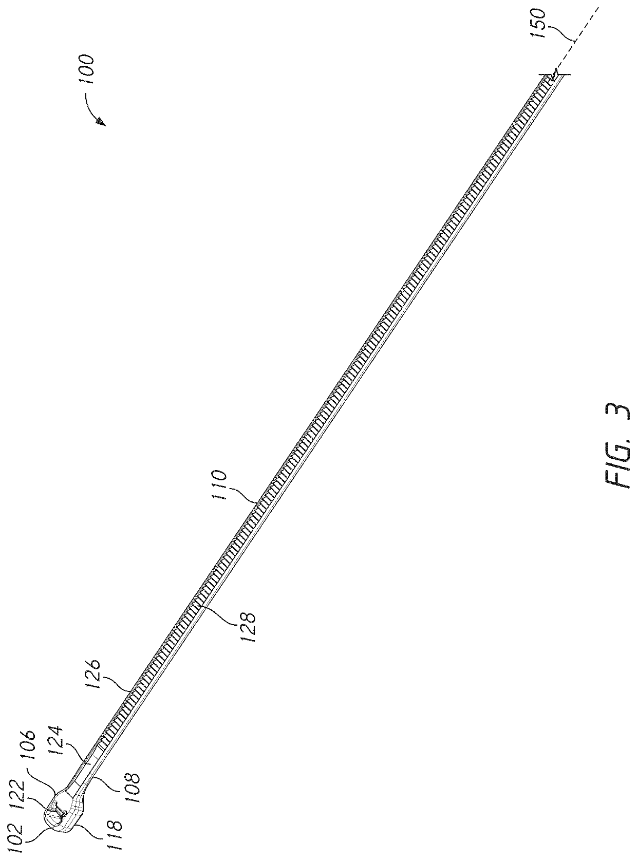
[0042]The systems and methods described herein relate to embodiments of bone ties, embodiments of bone ties inserters, and methods of use. The bone tie inserter can facilitate insertion of bone tie, as described herein. The bone tie can be inserted within a bone lumen, such as a bone lumen between adjacent vertebrae. The bone tie can be advanced by a bone tie advancer. The bone tie can be received by a bone tie retriever. In some embodiments, the bone tie pivots and / or rotates as the bone tie is withdrawn from the bone lumen between adjacent vertebrae.

[0043]1. Anatomy of the Spine

[0044]The vertebral c...


PUM


Abstract

Various embodiments of bone ties, bone tie inserters, and methods for treating the spine are provided. The bone tie can include a proximal end and a distal end. The bone tie can include a head section comprising a rounded head. The bone tie can include a neck section extending proximally from the head section. A bone tie inserter for placing a bone tie can also be provided. The bone tie inserter can include a bone tie advancer with a curved surface configured to guide a rounded head of a bone tie. The bone tie inserter can include a bone tie retriever configured to receive the rounded head of a bone tie. The bone tie is configured to pivot and / or rotate within the retriever portion of the bone tie inserter. The method can include forming a lumen in a first bone portion and a second bone portion. The bone tie can be configured to pivot and / or rotate as the bone tie retriever is withdrawn.

Description

CROSS-REFERENCE TO RELATED APPLICATIONS[0001]This application is a continuation in part of U.S. patent application Ser. No. 16 / 751,883, filed Jan. 24, 2020, which claims priority benefit to U.S. Provisional Patent Application No. 62 / 851,410, filed May 22, 2019, the entirety of which is hereby incorporated by reference herein.BACKGROUNDField[0002]Some embodiments described herein relate generally to systems and methods for performing spinal fusion and, in particular, to bone ties and bone tie inserters.Description of the Related Art[0003]Traumatic, inflammatory, and degenerative disorders of the spine can lead to severe pain and loss of mobility. According to some studies, back and spinal musculoskeletal impairments are the leading causes of lost work productivity in the United States. Pain as a result of some type of spinal impairment may have its source in a variety of pathologies or clinical conditions.[0004]One source for back and spine pain is related to degeneration of the face...

Claims


Application Information

Patent Timeline
Patent Type & Authority Patents(United States)
IPC IPC(8): A61B17/70
CPCA61B17/7064A61B17/7053A61B17/82A61B17/8861A61B2090/3966
Inventor SEMINGSON, TAYLOR
Owner SPINAL ELEMENTS INC
Why Eureka
Try Eureka