Bone tie methods

a bone fusion and bone fusion technology, applied in the field of bone fusion systems and bone fusion inserters, can solve the problems of little advancement in facet repair, reduced work efficiency, and severe pain and loss of mobility, and achieve the effect of facilitating pivoting and/or rotating, and correcting or improving the condition of the coronal plan

Active Publication Date: 2022-04-19
SPINAL ELEMENTS INC
View PDF647 Cites 5 Cited by
  • Summary
  • Abstract
  • Description
  • Claims
  • Application Information

AI Technical Summary

Benefits of technology

[0013]In some embodiments, the bone tie advancer comprises a channel to receive the neck section of the bone tie. In some embodiments, the bone tie advancer comprises a curve. In some embodiments, the bone tie advancer comprises a rounded section to abut the rounded head of the bone tie. In some embodiments, the bone tie retriever comprises an opening, wherein the neck section pivots, or pivots and rotates, from extending from the channel to extending through the opening. In some embodiments, the bone tie retriever comprises one or more retention features configured to retain the bone tie. In some embodiments, the bone tie retriever comprises a ledge. In some embodiments, the ledge facilitates pivoting and / or rotating of the rounded head of the bone tie.
[0014]In some embodiments, a method of treating vertebrae is provided. The method can include positioning a bone tie around a transverse process of a first vertebra. The method can include positioning the bone tie around a transverse process of a second vertebra. The method can include tightening the bone tie, wherein the bone tie is configured to correct or improve the condition of a coronal plane deformity.
[0018]In some embodiments, a method of treating vertebrae is provided. The method can include positioning a bone tie around a lamina of a first vertebra. The method can include positioning a bone tie around a lamina of a second vertebra. The method can include tightening the bone tie, wherein the bone tie is configured to correct or improve the condition of a sagittal plane deformity.

Problems solved by technology

Traumatic, inflammatory, and degenerative disorders of the spine can lead to severe pain and loss of mobility.
According to some studies, back and spinal musculoskeletal impairments are the leading causes of lost work productivity in the United States.
While many technological advances have focused on the spinal disc and artificial replacement or repair of the disc, little advancement in facet repair has been made.
This surgical procedure has a high rate of morbidity and can potentially lead to further clinical complications such as adjacent segment disorders.
This procedure is also not reversible.
Therefore, if the patient has an unsatisfactory result, they may be subject to additional surgical fusion procedures.

Method used


Image

  • Bone tie methods
  • Bone tie methods
  • Bone tie methods

Examples


Embodiment Construction

[0061]Although certain preferred embodiments and examples are disclosed below, it will be understood by those in the art that the disclosure extends beyond the specifically disclosed embodiments and / or uses of the invention and obvious modifications and equivalents thereof. Thus, it is intended that the scope should not be limited by the particular disclosed embodiments described below.

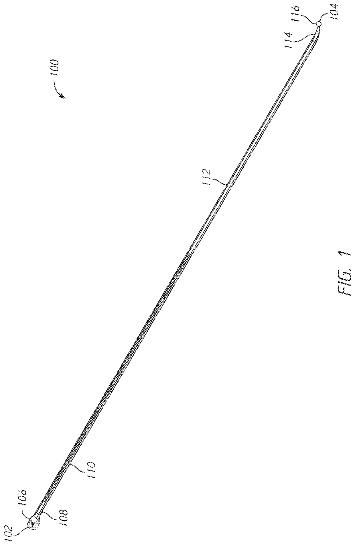
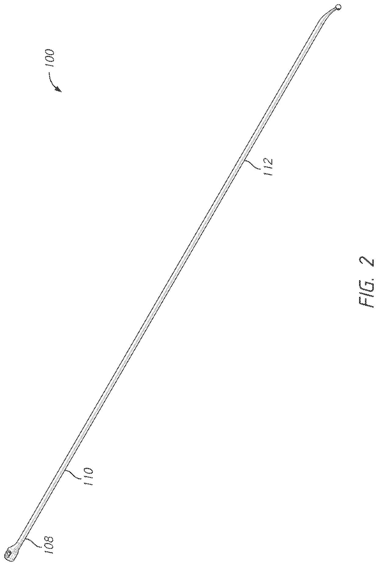
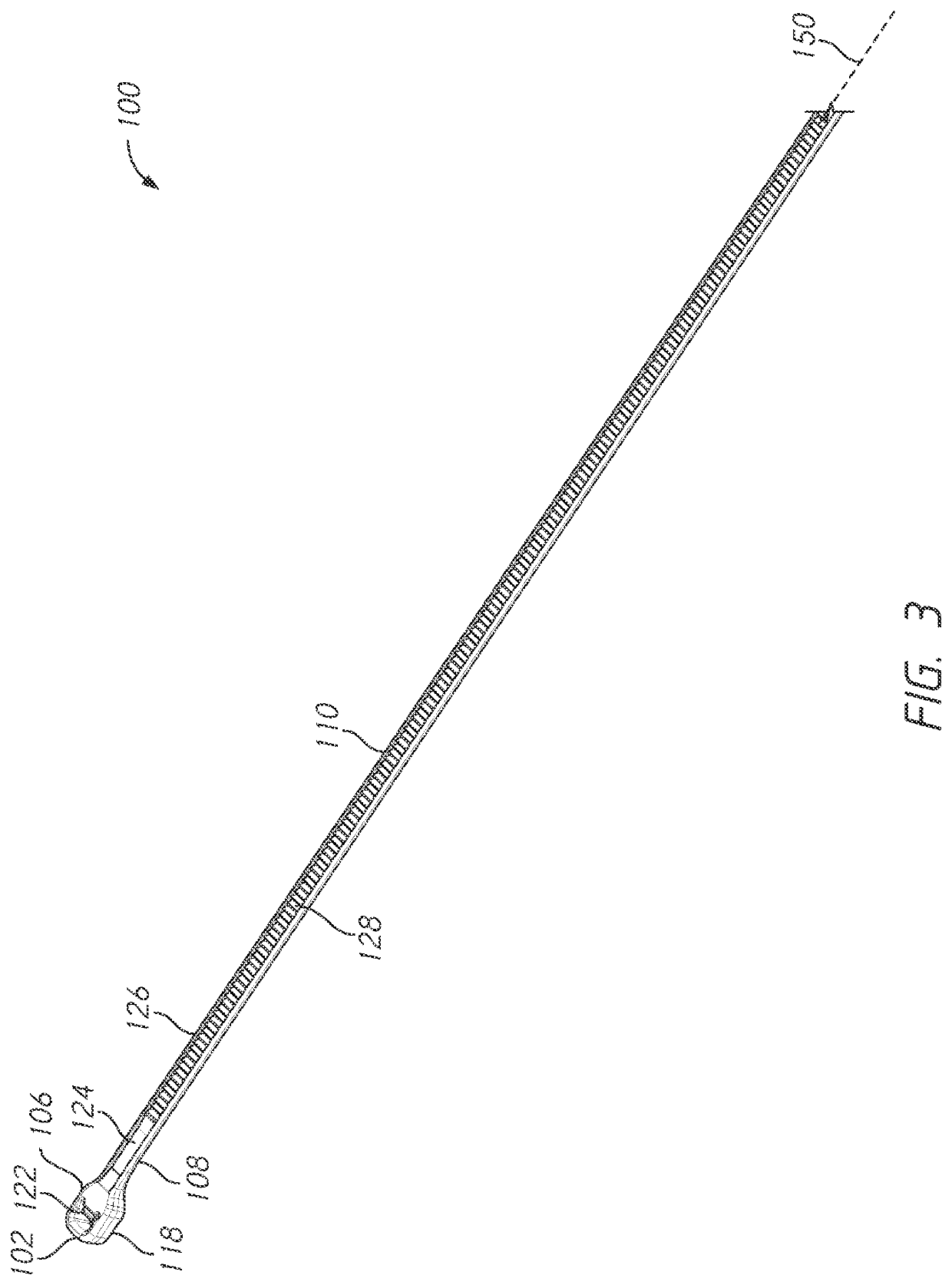
[0062]The systems and methods described herein relate to embodiments of bone ties, embodiments of bone tie inserters, and methods of use. The bone tie inserter can facilitate insertion of a bone tie, as described herein. The bone tie can be inserted within a bone lumen, such as a bone lumen between adjacent vertebrae. The bone tie can be advanced by a bone tie advancer. The bone tie can be received by a bone tie retriever. In some embodiments, the bone tie pivots and / or rotates as the bone tie is withdrawn from the bone lumen between adjacent vertebrae.

[0063]The methods can include wrapping the bone t...


PUM


Abstract

Various embodiments of bone ties, bone tie inserters, and methods for treating the spine are provided. The methods can include wrapping the bone tie around transverse processes of adjacent vertebrae to correct coronal plane deformity. The methods can include wrapping the bone tie around the spinous process of one vertebra and around the transverse process of a second adjacent vertebra to achieve rotational correction. The methods can include wrapping the bone tie around the lamina of adjacent vertebrae to achieve sagittal correction. The methods can include applying tension to the bone tie to set the sagittal correction. The methods can include passing the bone tie through a lumen in a vertebral body or a pedicle of the inferior vertebra and the lamina or articular process of the superior vertebra.

Description

CROSS-REFERENCE TO RELATED APPLICATIONS[0001]This application claims priority benefit to U.S. Provisional Patent Application No. 62 / 976,596, filed Feb. 14, 2020, the entirety of which is hereby incorporated by reference herein.FIELD[0002]Some embodiments described herein relate generally to systems and methods for performing spinal fusion and, in particular, to bone ties and bone tie inserters.DESCRIPTION OF THE RELATED ART[0003]Traumatic, inflammatory, and degenerative disorders of the spine can lead to severe pain and loss of mobility. According to some studies, back and spinal musculoskeletal impairments are the leading causes of lost work productivity in the United States. Pain as a result of some type of spinal impairment may have its source in a variety of pathologies or clinical conditions.[0004]One source for back and spine pain is related to degeneration of the facets of the spine or facet arthritis. Bony contact or grinding of degenerated facet joint surfaces may play a ro...

Claims


Application Information

Patent Timeline
Patent Type & Authority Patents(United States)
IPC IPC(8): A61B17/70A61B17/56A61F2/44A61B17/00
CPCA61B17/7053A61B17/7083A61B2017/00407A61B2017/564A61F2/4455A61B17/7064A61B17/842A61B17/82A61B17/8861A61F2/4611
Inventor BLAIN, JASONSEMINGSON, TAYLORBRADFORD, GREGORY THOMAS
Owner SPINAL ELEMENTS INC
Why Eureka
Try Eureka