Method for forming a short-radius bend in flanged sheet metal member

a technology of flanged sheet metal and short-radius bend, which is applied in the direction of metal-working apparatus, construction, building construction, etc., can solve the problems of excess material, unsightly wrinkling, and other portions of sheet metal members stretching

Inactive Publication Date: 2001-08-02
SIMPSON STRONG TIE
View PDF2 Cites 69 Cited by
  • Summary
  • Abstract
  • Description
  • Claims
  • Application Information

AI Technical Summary

Benefits of technology

[0013] It is an object of the present invention to form a bend in a sheet metal member having one or more flanges, the bend being transverse to the flange or flanges, without causing a wrinkling or buckling of the material of the flanges in the compressed areas.
[0014] It is a further object of the present invention to form a transverse, short-radius bend in an elongated sheet metal member having one or more flanges, creating continuous corner flanges free from wrinkles or puckering.
[0015] It is a further object of the present invention to form a transverse, tight-radius bend in an elongated sheet metal member having one or more flanges that are relatively high, creating wrinkle-free, continuous corner flanges.

Problems solved by technology

The problems caused by excess material are particularly acute in forming and wiping dies, operating at high frequencies.
In such presses, the material can also become caught, causing other portions of the sheet metal member to stretch.
Wrinkling is unsightly and is often perceived as a weak spot in the part.
Stretching can also create undesirable indentations in the corner of the flange.
Both wrinkling and stretching are not easily controlled between parts, such that there is a lack of uniformity between the parts.
The difficulties caused by the surplus material that develops can also prematurely age the press.
It is known in the prior art that excess material that develops between components of a die can cause "technical difficulties"which affects the operation of the press.
There are prior art methods of forming similar shapes in light gauge sheet metal; however, they suffer from various drawbacks.
However, draw-action dies are relatively slow compared to forming or wiping dies.
A number of other patented prior art processes form a transverse bend in a sheet metal part having corner flanges, however, these methods remove most or all of the material from the side flanges that is likely to be compressed.

Method used


Image

  • Method for forming a short-radius bend in flanged sheet metal member
  • Method for forming a short-radius bend in flanged sheet metal member
  • Method for forming a short-radius bend in flanged sheet metal member

Examples


Embodiment Construction

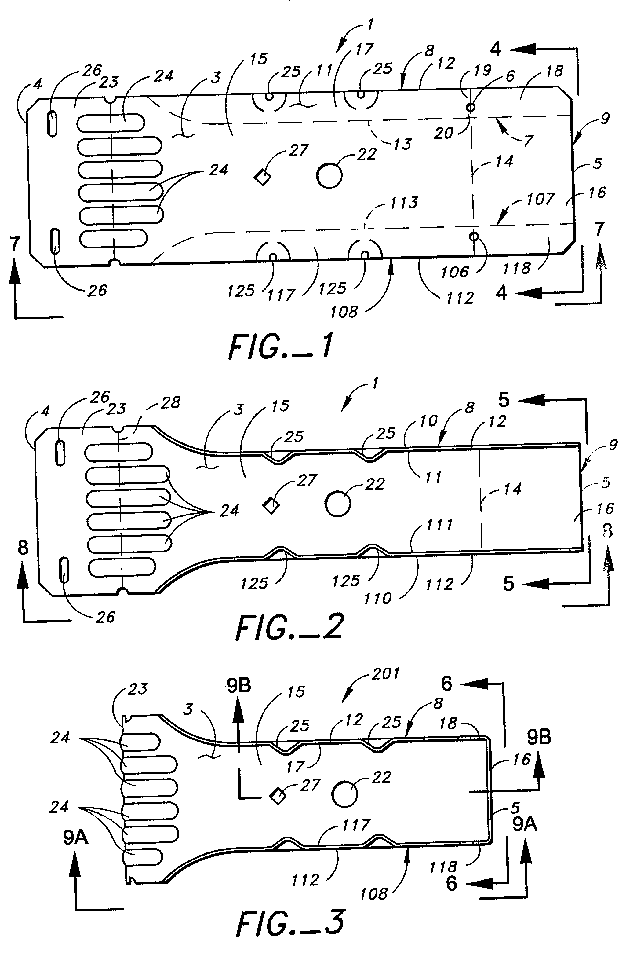
[0051] With reference to FIG. 1, the method of the present invention is performed on a piece 1 of bendable sheet material having a distal side 2, a proximal side 3 and first and second ends 4 and 5. In the first step of the process, a closed perimeter opening 6 is formed in the piece 1. The closed perimeter 6 opening has a first shape.

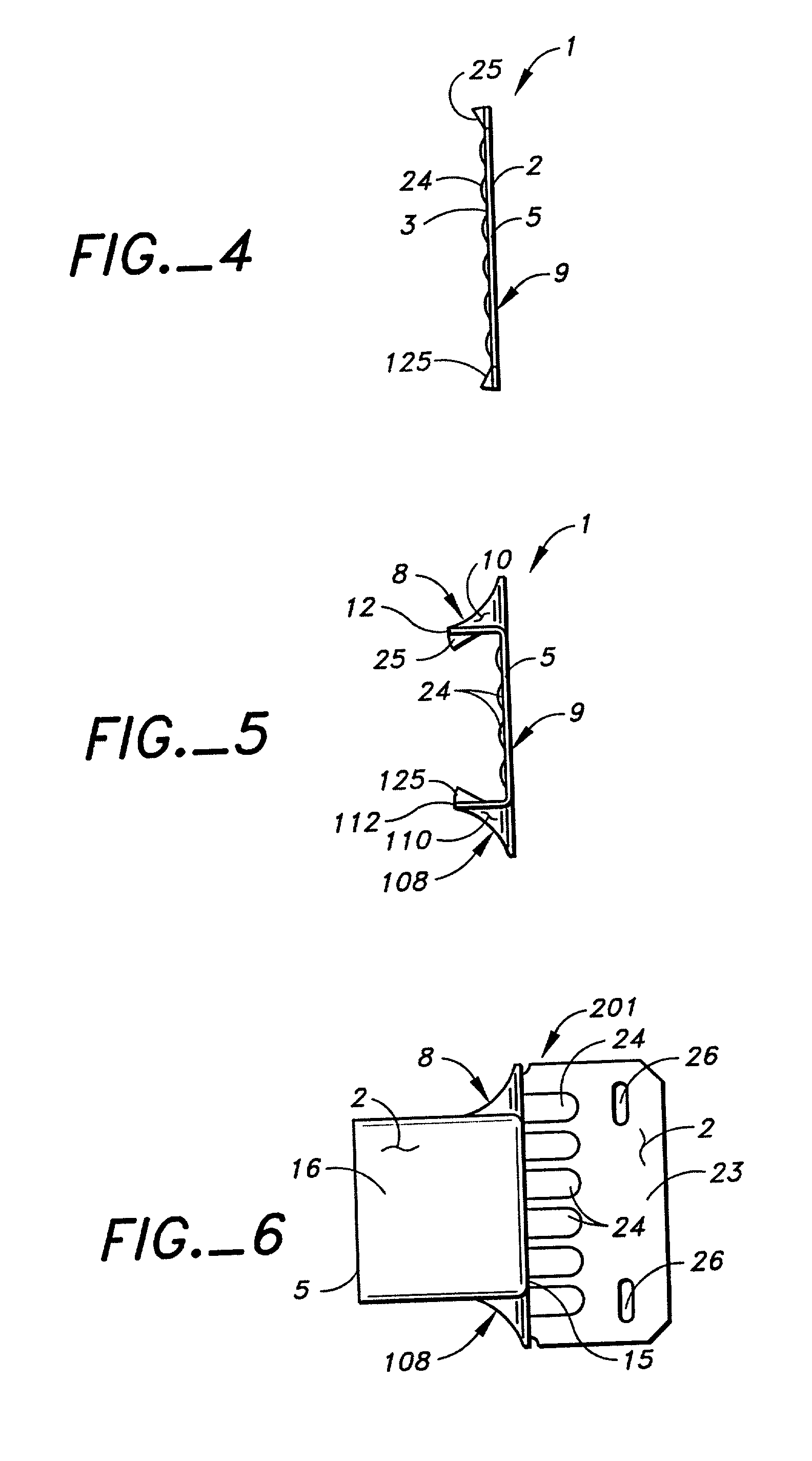
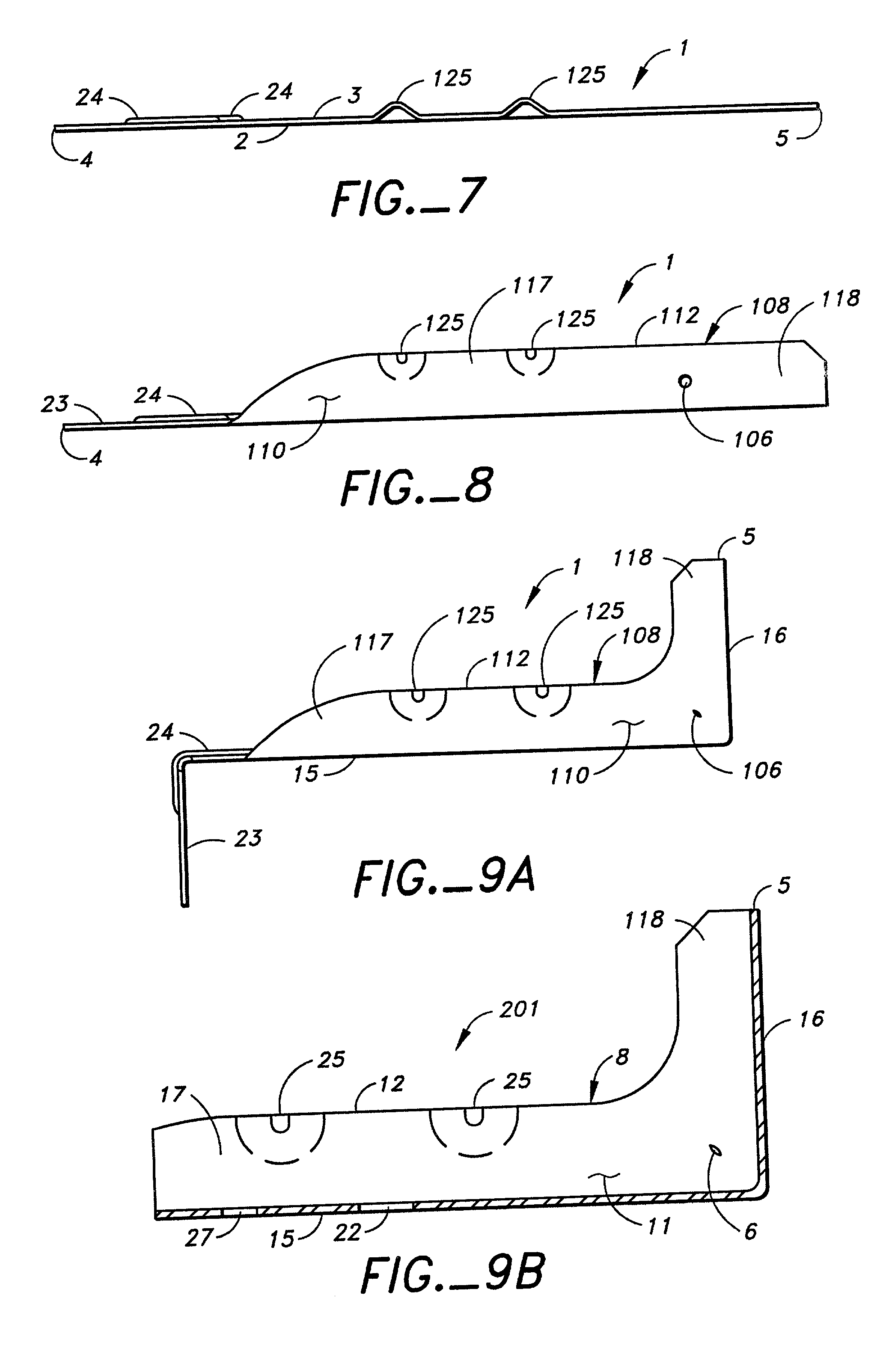
[0052] Next the piece 1 is bent along a flange bend line 7 so that the piece 1 adopts a first intermediate position. See FIG. 2. The flange bend line 7 divides the piece 1 into a flange 8 that contains the closed perimeter opening 6 and a web 9 to the other side of said flange bend line 7. The flange 8 has distal and proximal sides 10 and 11 corresponding to the distal and proximal sides 2 and 3 of the piece 1. The flange 8 also has a top 12 disposed away from the flange bend line 7 and a bottom 13 coincident with the flange bend line 7.

[0053] To complete the inventive method, the web 9 is bent along a transverse bend line 14 that divides the web 9 int...


PUM

PropertyMeasurementUnit
pressureaaaaaaaaaa
pressureaaaaaaaaaa
anglesaaaaaaaaaa

Abstract

One or more closed perimeter openings are formed in the compression area of a flange of a member that is to be bent transversely to the flange. The member is bent along a transverse bend line, and the flanges are bent inwardly on themselves. The bending of the member along the transverse bend line is done with a great force, and because portions of the side flanges are supported on their distal and proximal side, the material of the side flanges in the compression area plasticizes and flows into the closed perimeter opening, causing them to deform. Because the closed perimeter opening or openings are present, the side flanges are compressed in a more controlled manner, reducing cracking, wrinkling and thinning during the bending of the member along the transverse bend line.

Description

[0001] The present invention relates to a process of manufacture and the product made therefrom. It relates to shaping sheet metal blanks, particularly to operations in which a sheet metal member having a continuous flange is folded along a bend line transverse to the flange, creating a continuous corner flange. As an example, the present invention is useful in forming a joist hanger having a seat member, a back member connected thereto, and parallel continuous corner flanges also connecting the two members.[0002] When a sheet metal member having one or more flanges is bent transversely to the flange or flanges such that the flanges are swung inwardly on themselves, surplus material in the flanges along and near the bend develops. This excess material wants to fold over itself or crimp.[0003] The problems caused by excess material are particularly acute in forming and wiping dies, operating at high frequencies. For example, if the tolerances in the press are such that the flange is ...

Claims


Application Information

Patent Timeline
Patent Type & Authority Applications(United States)
IPC IPC(8): B21D5/02B21D11/10B21D53/74E04B1/26
CPCB21D5/0209B21D11/10B21D53/74E04B1/2608
Inventor LEEK, WILLIAM F.
Owner SIMPSON STRONG TIE
Why Eureka
Try Eureka