Canister

a canister and cylinder technology, applied in the field of canisters, can solve the problems of difficulty in enhancing the prevention of vapor discharg

Inactive Publication Date: 2001-11-15
AISAN IND CO LTD
View PDF0 Cites 25 Cited by
  • Summary
  • Abstract
  • Description
  • Claims
  • Application Information

AI Technical Summary

Problems solved by technology

Accordingly, it is difficult that enhancing the prevention of discharge of vapor is consistent with the shortening of the time of refueling.

Method used


Image

  • Canister
  • Canister
  • Canister

Examples


Embodiment Construction

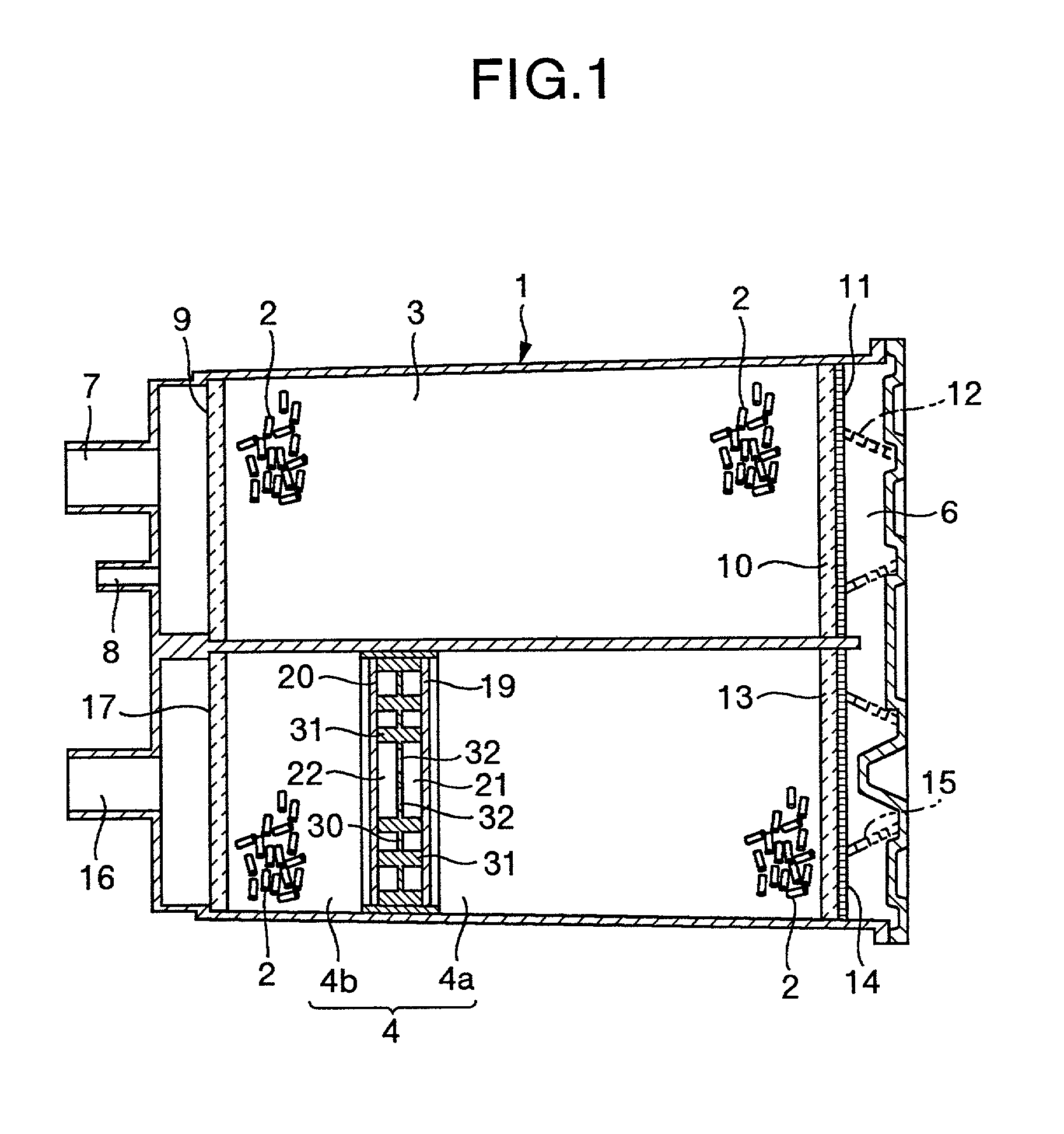
[0036] Explanation will be made of embodiments according to the present invention with reference to FIGS. 1 to 3.

[0037] The construction according to the present invention is the same as that of the conventional one shown in FIGS. 4 to 6, with only exception such that the structure of a plate 5 is different. Accordingly, like reference numerals are used to denote parts like to those shown in FIGS. 4 and 5 except the structure of the plate 30 according to the present invention, and explanation thereto will be omitted.

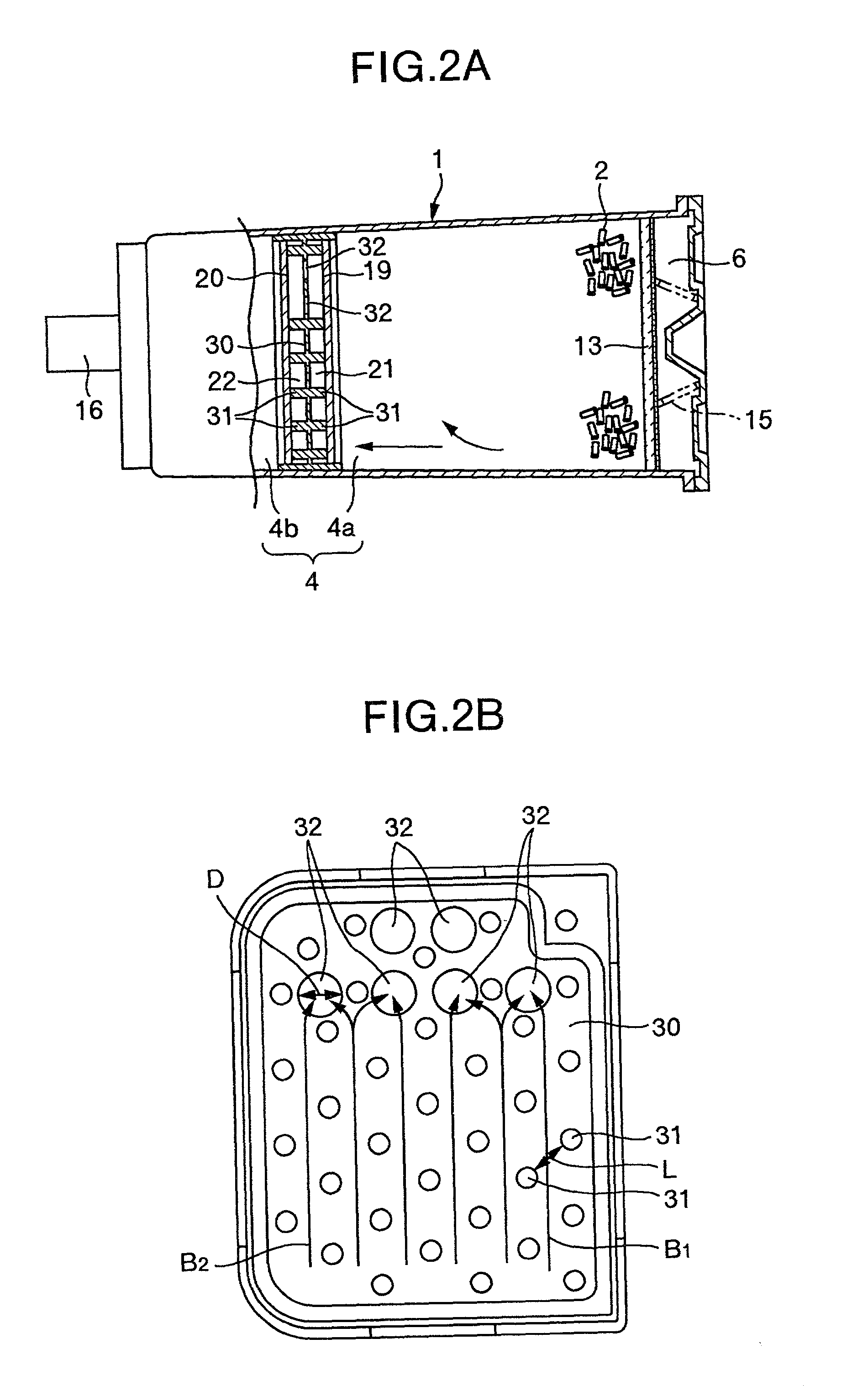
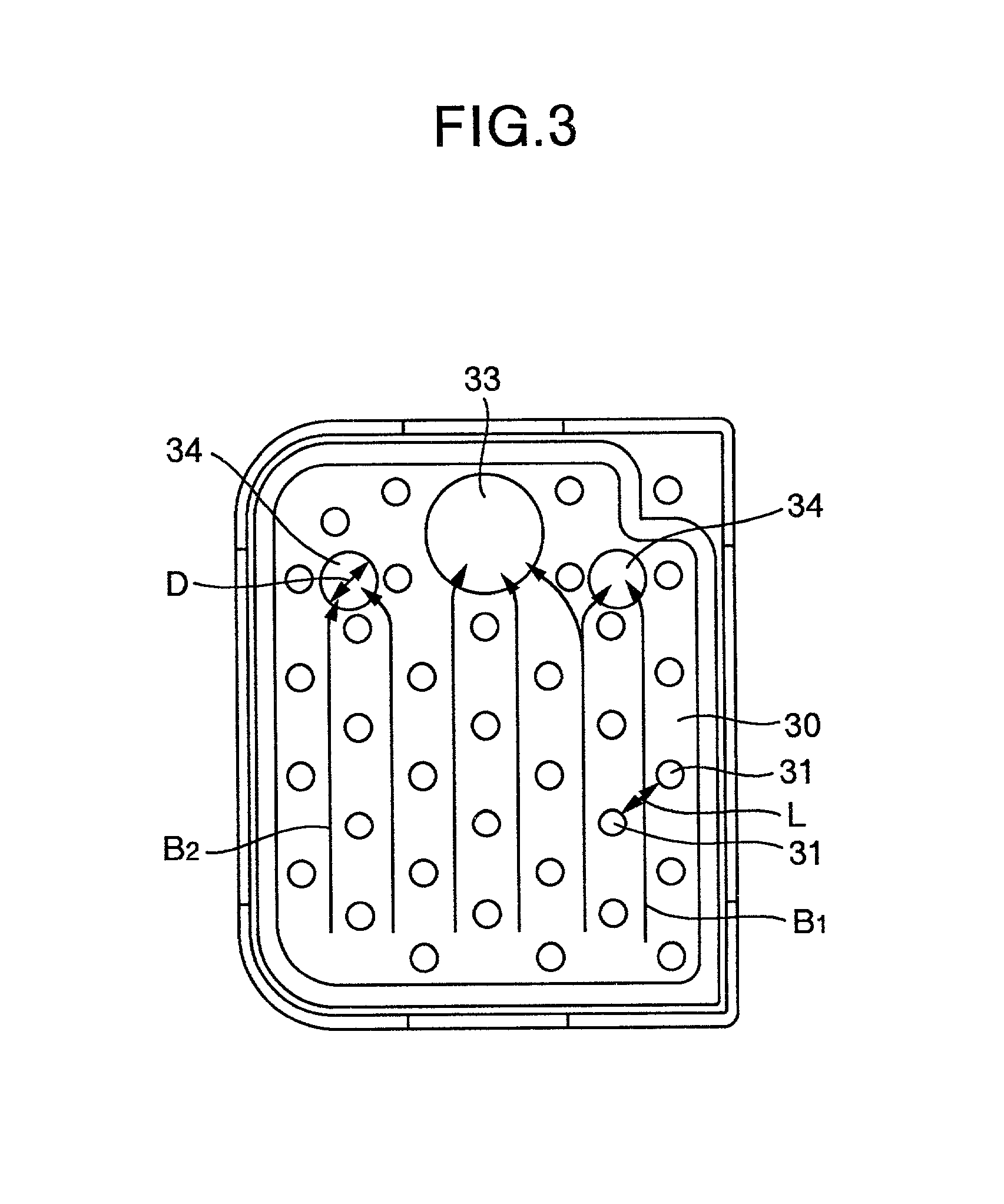
[0038] A plurality of filter support pins 31 similar to the conventional those are projected from both surfaces of a plate 30 located vertically in a subchamber 4, similar to the conventional filter support pins, having a predetermined distance (space) L, as shown in FIG. 2B.

[0039] Further, as constriction passage means, a plurality of constriction passages 32 are formed, piecing through the upper part of the plate 30, among the filter support pins as shown in FIG. 2B. I...


PUM

PropertyMeasurementUnit
inner diameteraaaaaaaaaa
diameteraaaaaaaaaa

Abstract

In order to aim at shortening the time of refueling by maintaining the function of prevention of discharge of vapor, similar to that of a conventional canister in the case of other than refueling during resting of an engine while the flow resistance in the canister becomes smaller during refueling, there is provided a canister in which a plate is vertically arranged in a chamber charged therein with absorbent in the canister, and filter support pins are projected from opposite surfaces of the plate while filters are arranged at the tip end faces of the filter support pins, and in which a plurality of constriction passages are formed being arranged in a horizontal direction only in the upper part of the plate.

Description

[0001] The present invention relates to a canister located in an evaporated fuel processing device.RELATED ART[0002] Conventionally, as a canister which is located in an evaporated fuel processing device for preventing evaporated fuel (vapor) in a fuel tank on an automobile from leaking into the atmosphere, there has been proposed a canister of such a type that copes with an ORVR (Onboard Refueling Vapor Recovery) regulation, in which a plate is arranged in a absorbent charging chamber of the canister, and a constriction passage is formed in the plate in order to trap and process vapor in the fuel tank, in particular during refueling, without the vapor leaking into the atmosphere. This canister is disclosed in, for example, JP-A-06-249088 and JP-A-08-189428.[0003] In such an ORVR regulation type canister, a conventional structure of the canister in which the above-mentioned plate is vertically arranged is shown in FIGS. 4 to 6.[0004] The canister 1 shown in FIGS. 4 to 6, is composed...

Claims


Application Information

Patent Timeline
Patent Type & Authority Applications(United States)
IPC IPC(8): B01D53/04F02M25/08
CPCB01D53/0415B01D2253/102B01D2259/4516B01D2259/4566F02M25/0854
Inventor MORIYAMA, MASATOSHIYOSHIDA, TOSHIO
Owner AISAN IND CO LTD
Why Eureka
Try Eureka