Sanding truck sandbagging apparatus

Inactive Publication Date: 2001-11-22
MALONE MORRIS J +2
View PDF0 Cites 17 Cited by
  • Summary
  • Abstract
  • Description
  • Claims
  • Application Information

AI Technical Summary

Benefits of technology

0017] FIG. 4 is an illustration showing the control box and control valve system connected to the t

Problems solved by technology

Large sandbagging apparatus, such as those shown in U.S. Pat. No. 6,112,956 which are designed to manufacture large quantities of sandbags, are too

Method used


Image

  • Sanding truck sandbagging apparatus
  • Sanding truck sandbagging apparatus
  • Sanding truck sandbagging apparatus

Examples


Embodiment Construction

)

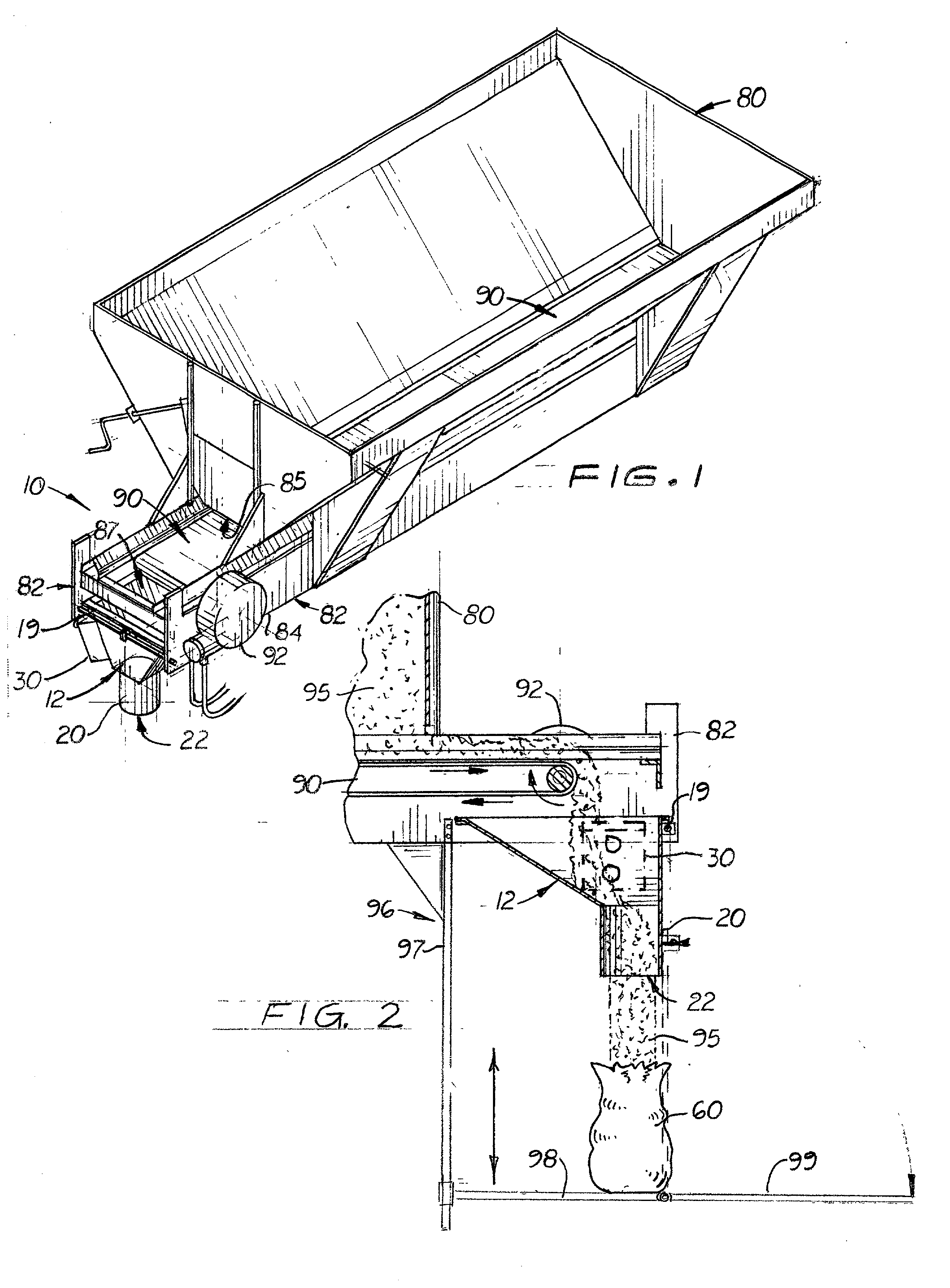
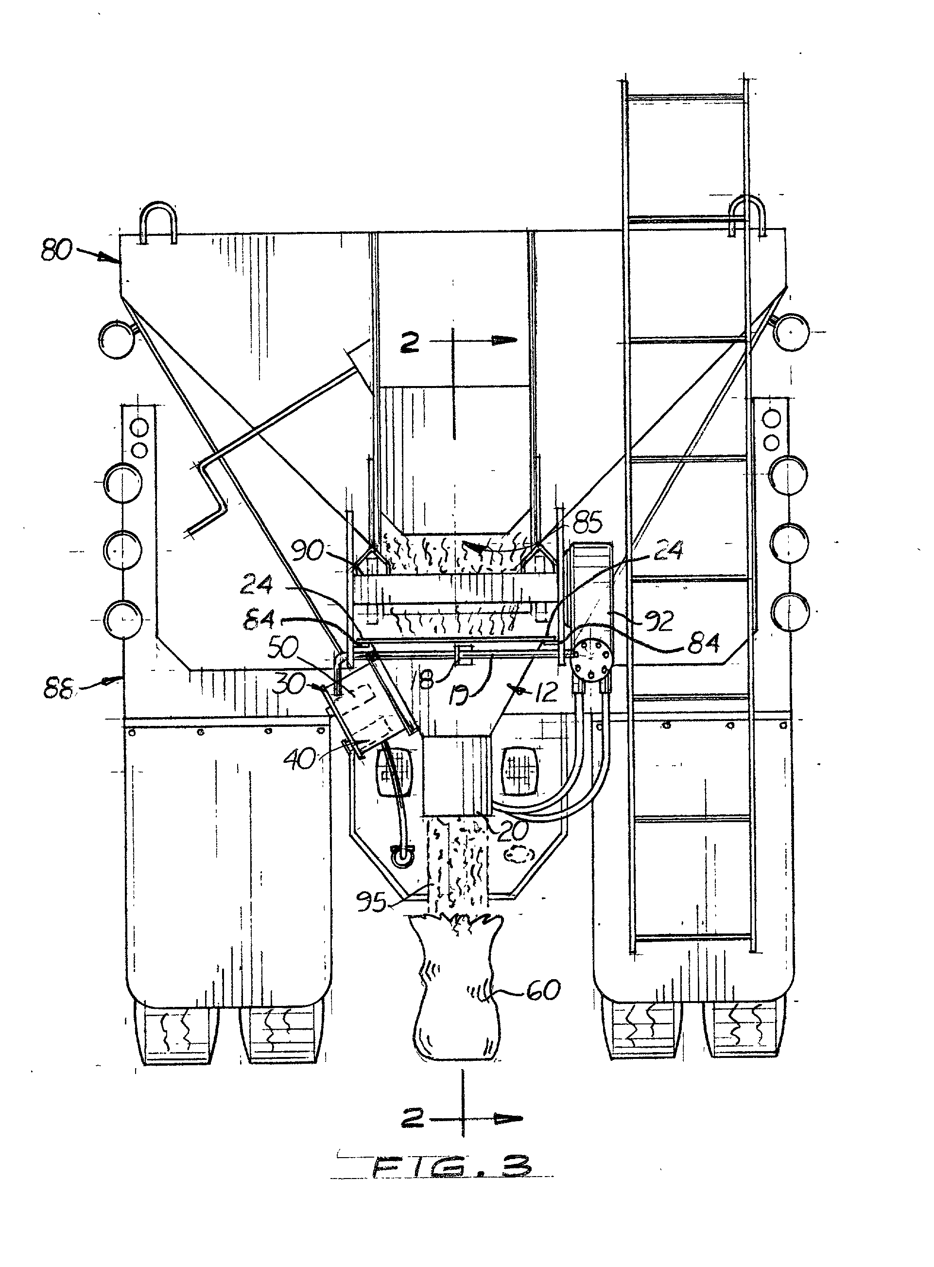
[0018] Referring to the accompanying FIGS., there is shown and described a sandbagging manufacturing apparatus 10 designed to be used with a standard sanding truck 83 that transports a large hopper 80 with a hydraulically controlled conveyor belt 90 disposed longitudinally on the bottom of the hopper 80 that, during use, delivers sand 95 through the hopper's rear opening 85. The truck 83 also includes a rearward extending framework 82 normally used to hold a broadcast spreader (not shown) behind and below the rear opening 85.

[0019] As shown in FIGS. 2 and 3, the small hopper 12 includes two laterally extending plate members 24 designed to slide into two L-shaped brackets 84 located on the framework 82. Formed on the small hopper 12 is a vertically aligned chute 20 which directs discharged sand 95 from the rear opening 85 into sandbags 60 positioned below the lower opening 22 on the chute 20.

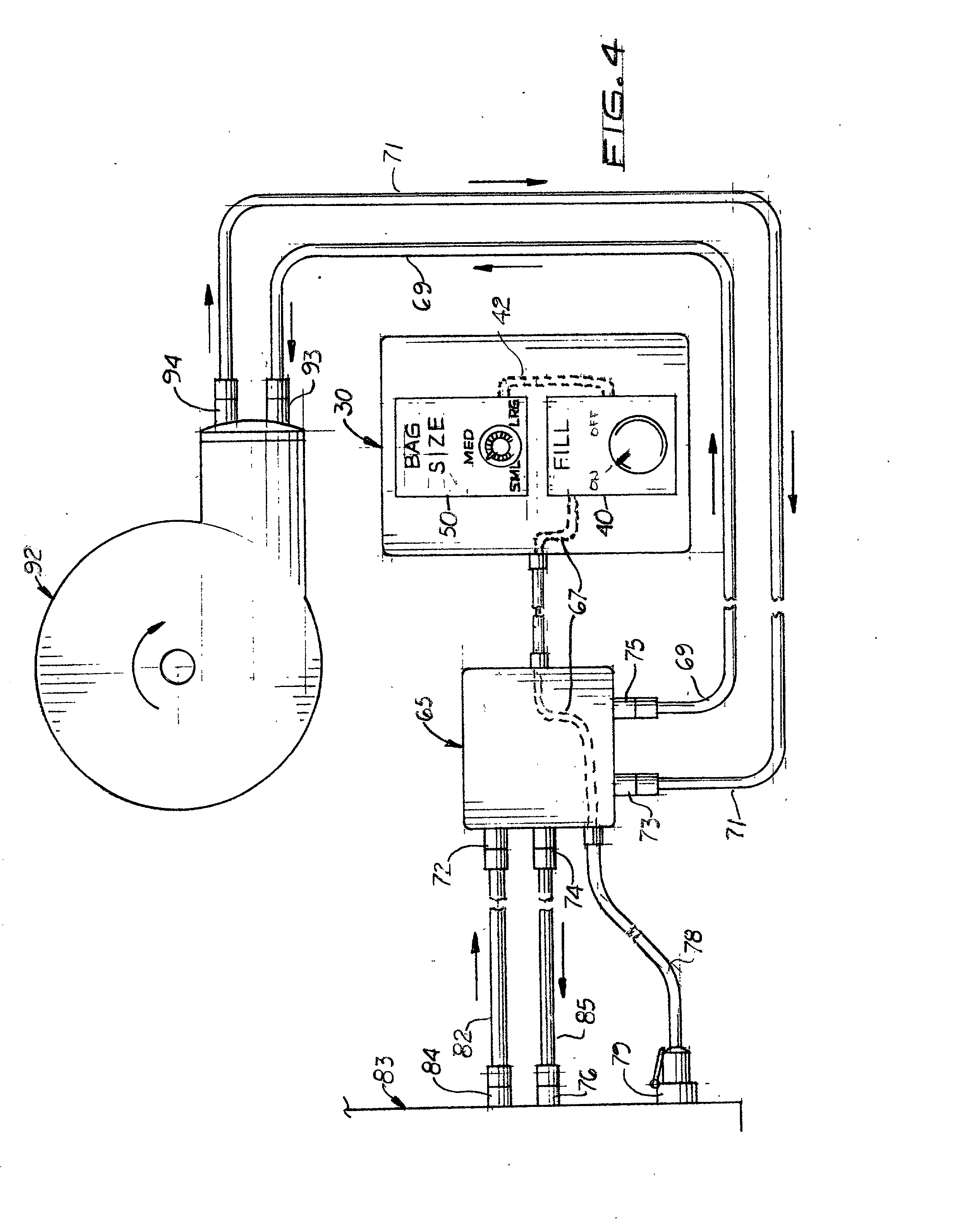
[0020] As shown in FIGS. 3 and 4, the apparatus 10 also includes a rear mounted control box ...


PUM

PropertyMeasurementUnit
Timeaaaaaaaaaa

Abstract

A sandbagging manufacturing apparatus designed to be used with standard sanding trucks normally used with a broadcast spreader. The truck includes a large hopper with a hydraulically controlled conveyor belt located longitudinally inside the large hopper that delivers sand to a rear opening. Located below the rear opening is rigid framework used to hold the broadcast spreader. The apparatus includes a small hopper selectively attached to the framework below the hopper's rear opening. The small hopper is designed to slide into brackets formed on the framework so that the small hopper and broadcast spreader may be easily exchanged. A vertically aligned chute is attached to the small hopper through which sand falls to fill sandbags. The apparatus also includes a control box designed to control the operation of the conveyor belt. Located in the control box is an adjustable electric timer that controls the length of time the conveyor belt is activated which, in turn, controls the amount of sand delivered to the hopper's rear opening area. A main on-off switch is provided on the outside surface of the control box, which controls activation of the conveyor belt and the timer.

Description

[0001] This is a utility paten application based on a provisional patent application (Ser. No. 60 / 204,501) filed on May 16, 2000.[0002] 1. Field of the Invention[0003] This invention pertains to sandbagging apparatus for making individual sandbags and more particularly, to sandbagging apparatus that attach to the back of a standard roadway sanding truck.[0004] 2. Description of the Related Art[0005] Many municipalities use sanding trucks to spread sand on roadways during snowy or icy roadway conditions. Standard sanding trucks include a large hopper located on the bed of the truck with a selectively operated gate over the rear opening of the hopper and a hydraulic control conveyor belt located along the bottom of the hopper that delivers sand to the rear opening. Located behind and below the rear opening is a broadcast spreader that receives sand from the rear opening and evenly distributes it over the roadway immediately behind the truck.[0006] The broadcast spreader is a relativel...

Claims


Application Information

Patent Timeline
IPC IPC(8): B60P1/38G01F11/00
CPCB60P1/38G01F11/003
Inventor MALONE, MORRIS J.MALONE, MORRIS W.MALONE, VIOLA C.
Owner MALONE MORRIS J
Why Eureka
Try Eureka