Fixation device

Inactive Publication Date: 2001-12-13
BALLIER ROLAND
View PDF0 Cites 32 Cited by
  • Summary
  • Abstract
  • Description
  • Claims
  • Application Information

AI Technical Summary

Benefits of technology

0010] The fixation device offers a minimally invasive alternative to surgery of fractures of bones such as, for example, the tibia. The individual fragments are secured in the area of the cortex in each instance without the medullary cavity being opened (so-called pinless nail method). The fixation device can be applied rapidly and simply because of the fixation pin applicator provided according to the invention, and permits intra operative and postoperative repositioning of the device and of the b

Problems solved by technology

This fixation of the clamping pins

Method used


Image

  • Fixation device
  • Fixation device
  • Fixation device

Examples


Embodiment Construction

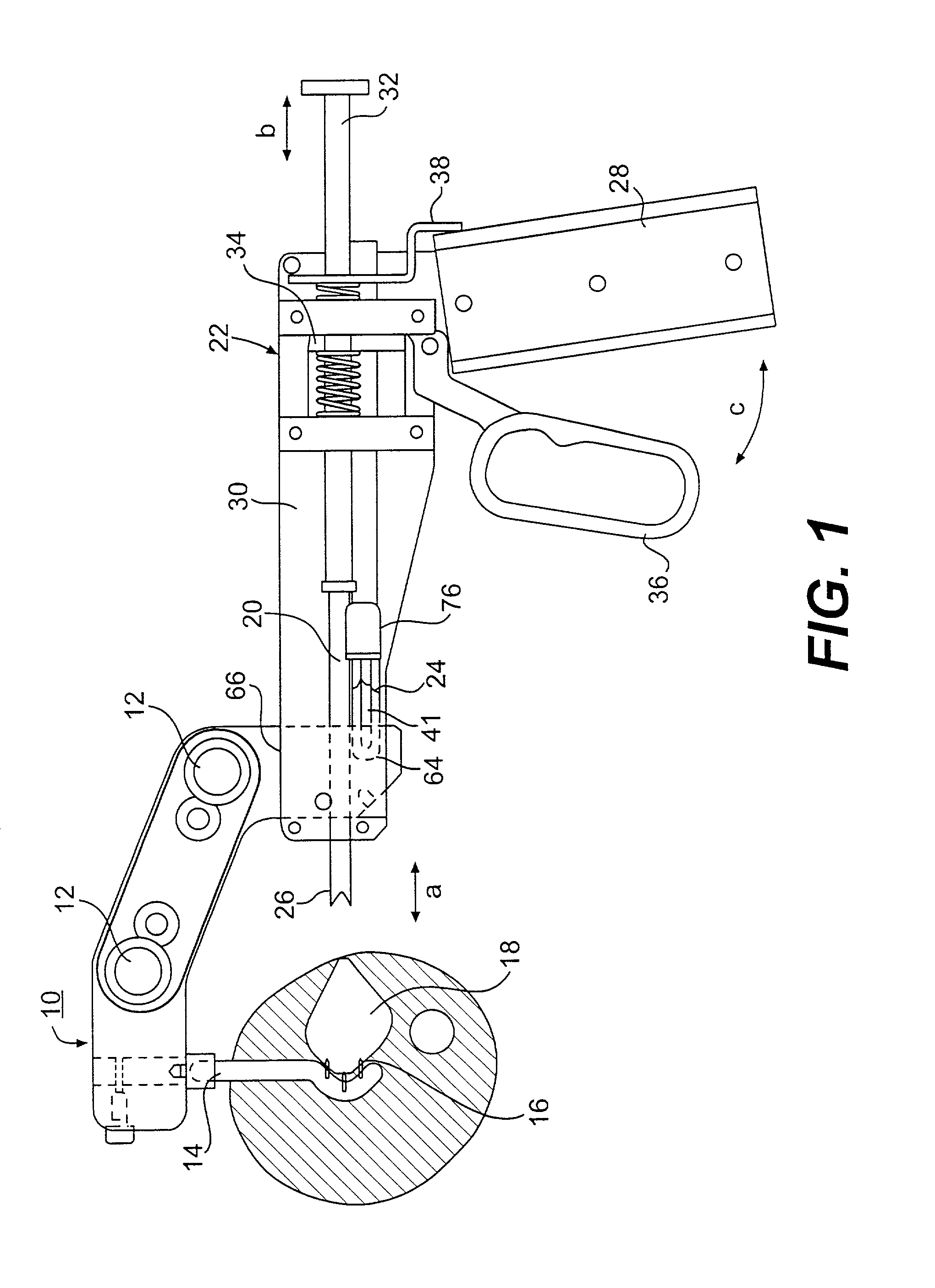
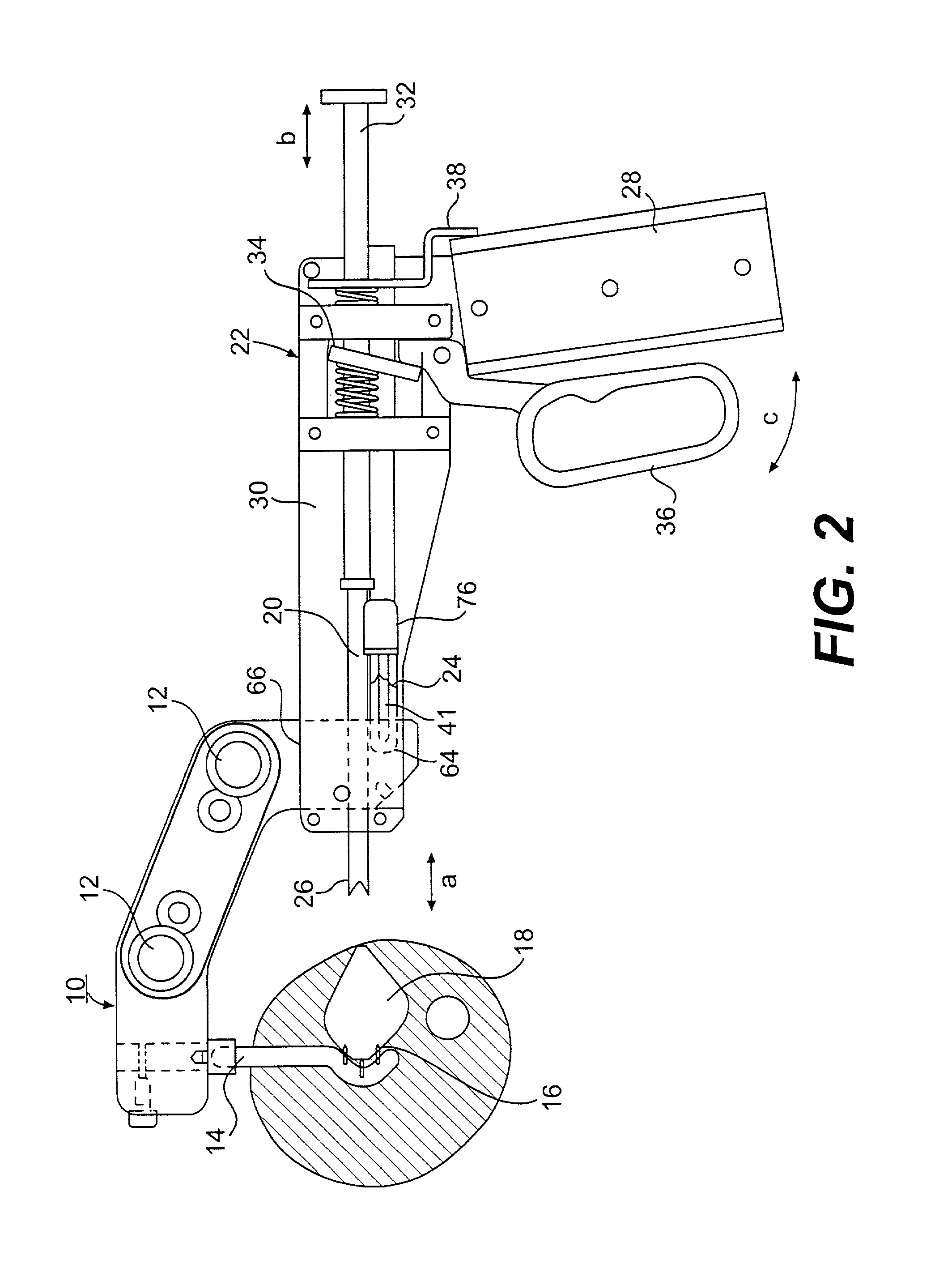
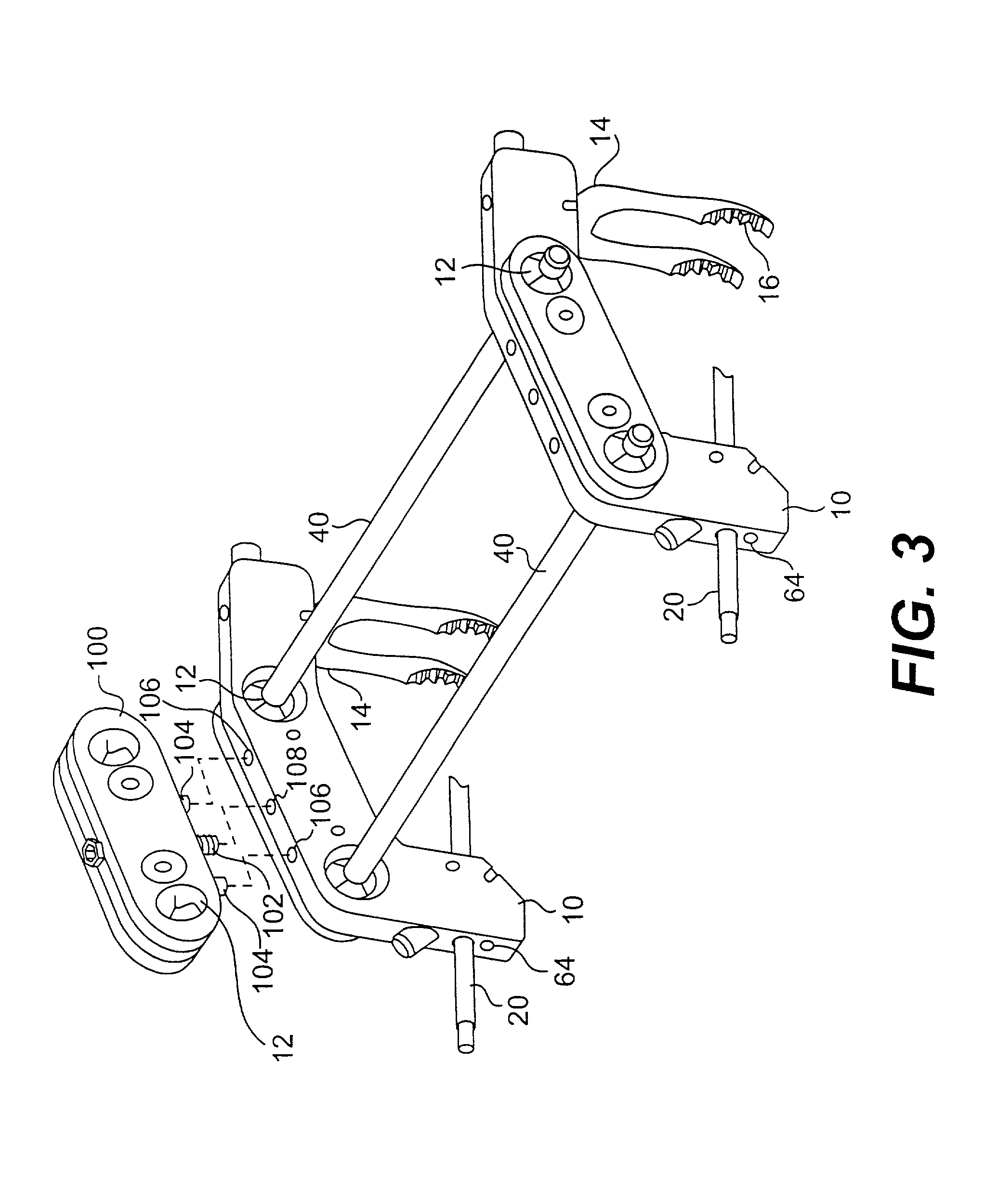
[0031] The fixation device is formed from a plurality of clamping jaws. FIGS. 1 and 2 show one such clamping jaw 10, connected to a fixation pin applicator 22. As shown in FIGS. 3 and 4, clamping jaws 10 can be formed from straight sections bent at an angle with respect to one another, but can also be formed of sector rings or of curved segments. Clamping jaws 10 are connected by axial rods 40 that are axially displaceable in the clamping jaws and can be pivoted relative to the plane of clamping jaws 10. As a result, simple three-dimensional adjustment of clamping jaws 10 relative to one another is possible.

[0032] FIGS. 3 and 4 show one embodiment of an arrangement of two clamping jaws 10 and two axial rods 40. Axial rods 40 can pivot and can translate axially within clamping receptacles 12. Once clamping jaws 10 are positioned in a desired relative position, the axial rods 40 can be fixed to the clamping jaws 10 in a manner to be described later, so as to maintain the desired relat...


PUM


Abstract

The invention relates to a fixation device with clamping jaws and with rods connecting the clamping jaws, said rods being adjustable axially and angularly for positioning relative to the clamping jaws and clampable in the desired position, and with fixation and retaining pins that are receivable in a clampable fashion in the clamping jaws. According to the invention, a fixation pin applicator can be connected in a releasable fashion to the clamping jaws. A fixation pin can be brought into a desired position by means of the fixation pin applicator.

Description

[0001] This is continuation of U.S. Ser. No. 09 / 400,436, filed on Sep. 21, 1999, which is a continuation-in-part of U.S. Ser. No. 09 / 011,924, filed on Jun. 8, 1998.[0002] The invention consists of a fixation device used to immobilize portions of a fractured bone relative to one another, and more specifically to a device to immobilize such portions of fractured bone by attaching an adjustable rigid frame to the fractured bone.DESCRIPTION OF RELATED ART[0003] A fixation device is known from DE 41 13 083 A1. This fixation device has three or four rings used as clamping jaws, said rings being designed as either closed or sector rings. The rings are connected with one another by rods. For mutual positioning of the rings, the rods are axially displaceable and pivotable with respect to the rings and can be clamped in position respective to the rings. Holders are provided on the rings for bone wires or bone fixation and retaining pins.[0004] The known fixation device permits free relative m...

Claims


Application Information

Patent Timeline
IPC IPC(8): A61B17/16A61B17/62A61B17/88
CPCA61B17/1697A61B17/645A61B17/6466A61B17/8872
Inventor BALLIER, ROLAND
Owner BALLIER ROLAND
Why Eureka
Try Eureka