
Concentrical slot telecommunications equipment enclosure

Inactive Publication Date: 2002-01-24
SPECIAL PRODS
View PDF0 Cites 16 Cited by
  • Summary
  • Abstract
  • Description
  • Claims
  • Application Information

AI Technical Summary

Problems solved by technology

Electricity to power fans or other artificial cooling means is typically not available to the enclosures and so heat dissipation must be accomplished naturally.
One problem with existing enclosure designs is that they do not make the most efficient use of natural cooling mechanisms.
Thus, for example, cooling problems are exacerbated in enclosures wherein the repeater cards are arranged within the housing such that generated heat is retained and transferred between adjacent cards and equipment rather than to the environment surrounding the enclosures.
Unfortunately, this arrangement requires that the electronic equipment be removed from the enclosure or its function otherwise disrupted whenever the surge protection mechanism is replaced.

Method used


Image

  • Concentrical slot telecommunications equipment enclosure
  • Concentrical slot telecommunications equipment enclosure
  • Concentrical slot telecommunications equipment enclosure

Examples


Embodiment Construction

.

BRIEF DESCRIPTION OF THE DRAWING FIGURES

[0012] A preferred embodiment of the present invention is described in detail below with reference to the attached drawing figures, wherein:

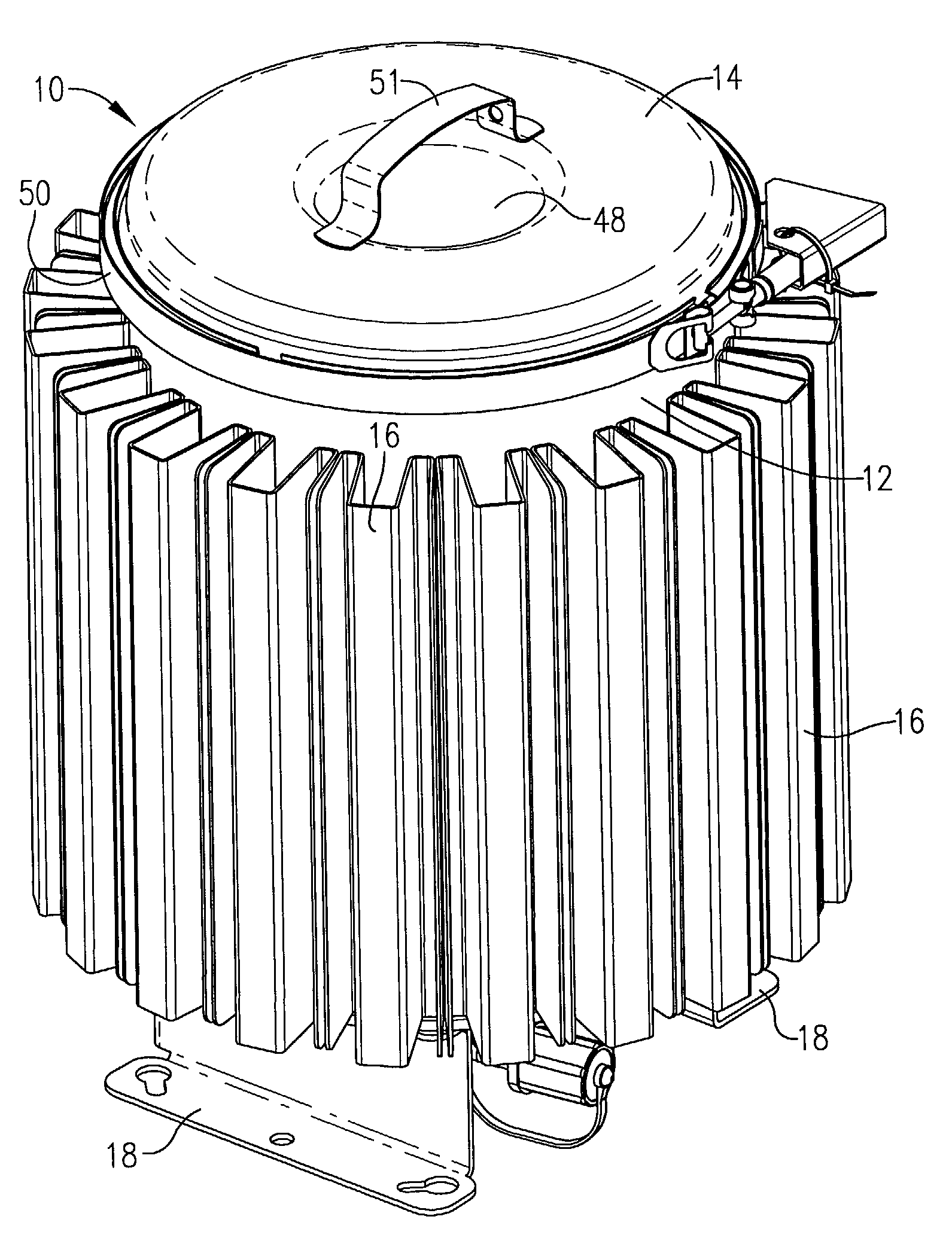
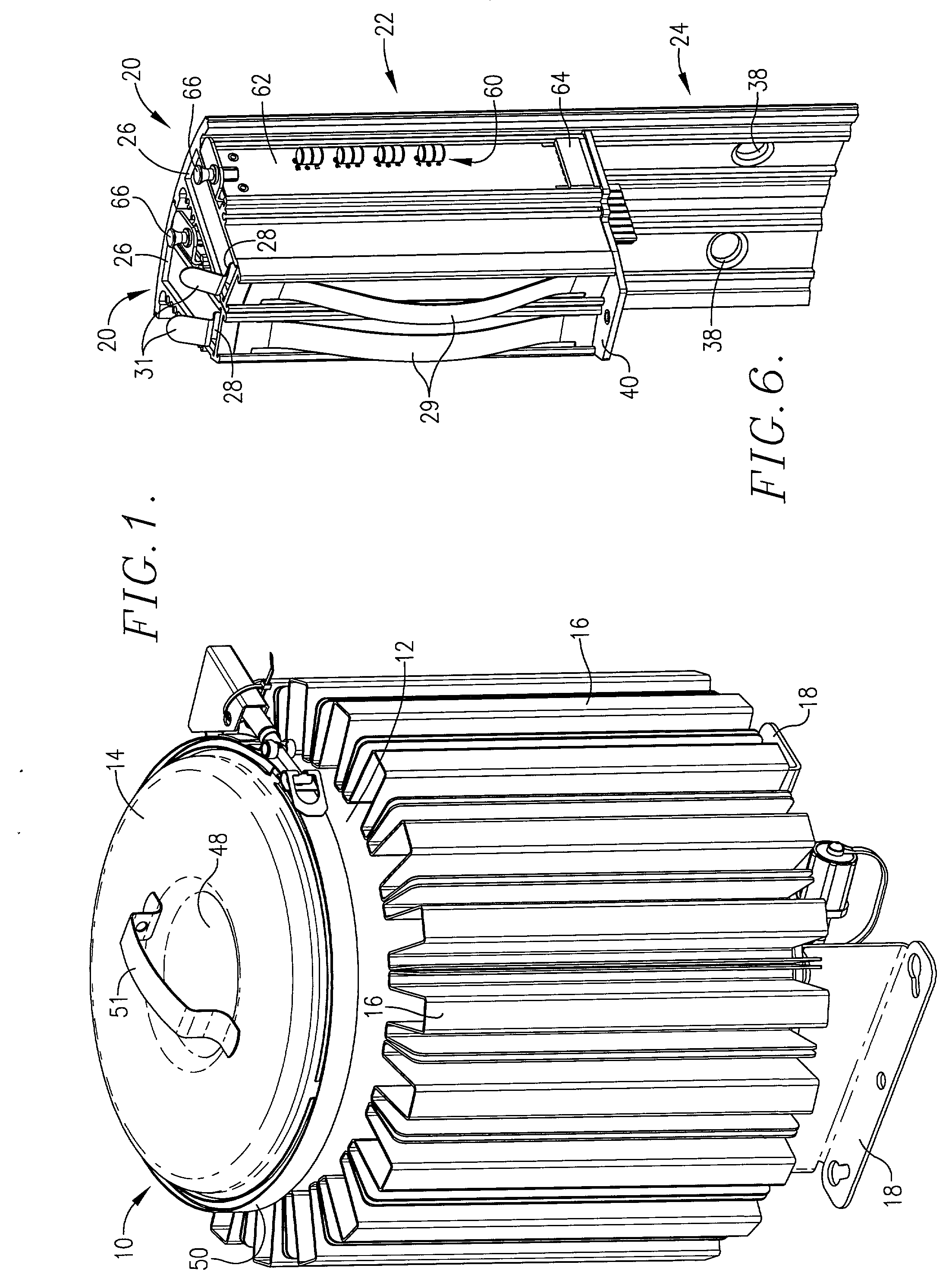
[0013] FIG. 1 is an isometric view of a telecommunications equipment enclosure constructed in accordance with a preferred embodiment of the present invention;

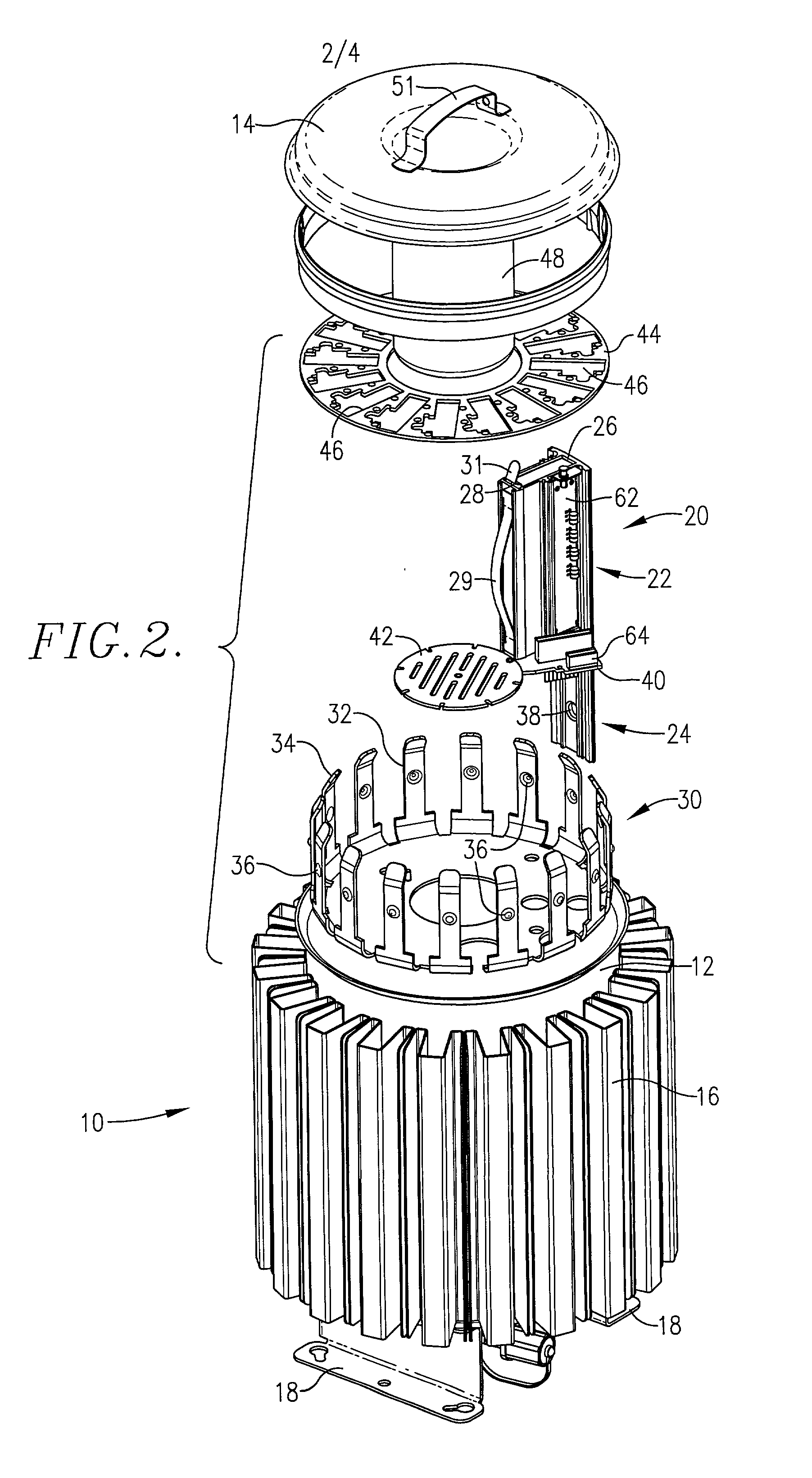
[0014] FIG. 2 is an exploded isometric view of the enclosure of FIG. 1;

[0015] FIG. 3 is a cross-sectional view of the enclosure of FIG. 1;

[0016] FIG. 4 is a top view of the enclosure with the top cover removed;

[0017] FIG. 5 is cross-sectional view of a card-receiving sleeve for use with the enclosure of FIG. 1; and

[0018] FIG. 6 is an isometric view of a card-receiving sleeve for use with the enclosure of FIG. 1.

DETAILED DESCRIPTION OF A PREFERRED EMBODIMENT

[0019] Referring to FIG. 1, a telecommunications equipment enclosure 10 is shown constructed in accordance with a preferred embodiment of the present invention, and operable to protectively house a...


PUM


Abstract

A telecommunications equipment enclosure (10) that dissipates into the ambient environment heat internally generated by signal repeater cards and other electronic equipment stored therein, thereby prolonging equipment life and preventing premature failure due to damaging levels of retained heat. Equipment-receiving sleeves (20) are removably arranged concentrically about the interior of a cylindrical housing (12). The housing (12) is fitted with a lid (14) having a cylindrically protruding portion (48). Cooling fins (16) operable to conduct and dissipate heat are attached to the exterior of the housing (12). Each sleeve (20) is able to conduct heat away from the heat-generating equipment received therein, and to transfer the heat along two distinct thermally conductive pathways. Surge protection (60) is provided on a removable circuit board (62) located adjacent each sleeve (20) and replaceable without removing the sleeve (20) or otherwise disrupting functioning of the cards or other electronic equipment.

Description

[0001] This application claims priority benefit, with regard to all common subject matter, of provisional application titled "Radial Slot Telecommunications Enclosure", Ser. No. 60 / 182,299, filed Feb. 14, 2000, and provisional application titled "Enclosure for Telecommunications Equipment", Ser. No. 60 / 221,235, filed Jul. 7, 2000, both of which are hereby incorporated into the present application by reference.[0002] 1. Field of the Invention[0003] The present invention relates to telecommunications equipment. More particularly, the present invention relates to a telecommunications equipment enclosure for protectively housing and cooling heat-generating electronic equipment such as signal repeaters. p 2. Description of the Prior Art[0004] Telecommunications signal repeaters and other electronic equipment used by providers of telecommunications services are typically housed in enclosures that are mounted to telephone poles or placed next to buildings or in manholes. The enclosures mus...

Claims


Application Information

Patent Timeline
IPC IPC(8): H04Q1/10H04Q1/14H05K5/06H05K7/20
CPCH04Q1/10H04Q1/143H04Q2201/06H05K5/068H05K7/2049H04Q1/035H04Q1/025
Inventor HUTCHISON, RANDALL D.SHIFFBAUER, ROBERTSMITH, KEVAN
Owner SPECIAL PRODS
Learn More