High security side bar lock

a side bar lock, high security technology, applied in the field of cylinder locks, can solve the problem of eliminating the possibility of defeating a cylinder lock

Inactive Publication Date: 2002-05-16
INT SECURITY PROD
View PDF0 Cites 43 Cited by
  • Summary
  • Abstract
  • Description
  • Claims
  • Application Information

AI Technical Summary

Problems solved by technology

The selection of a complex keyway profile and/or variation of the number and orientation of the pin tumbler arrays will not eliminate the possibility of defeat of a cylinder lock.
This fact, in part, results from the ready availability of key blanks having blades which, either as manufactured or as shaped using con

Method used


Image

  • High security side bar lock
  • High security side bar lock
  • High security side bar lock

Examples


Embodiment Construction

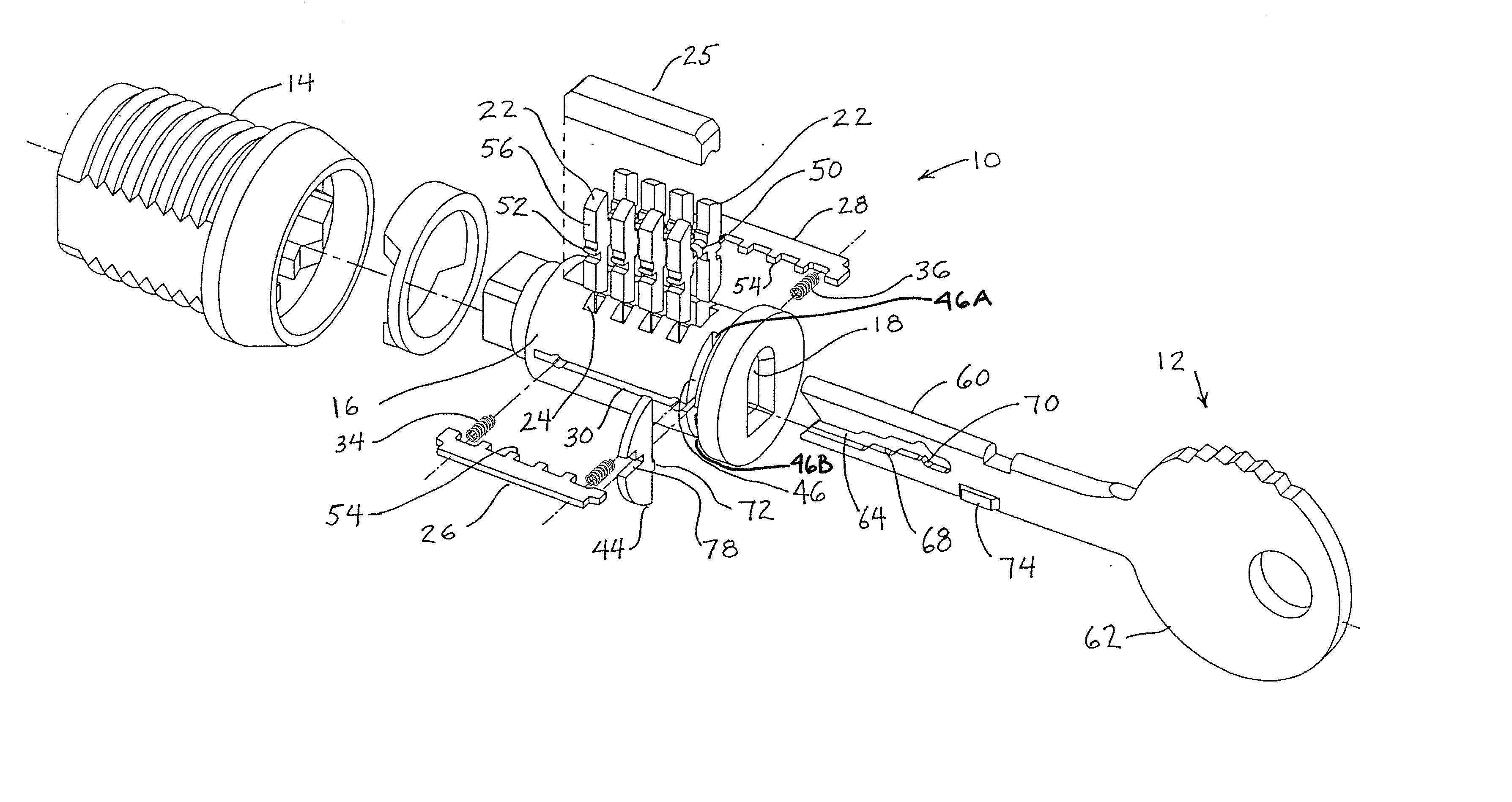
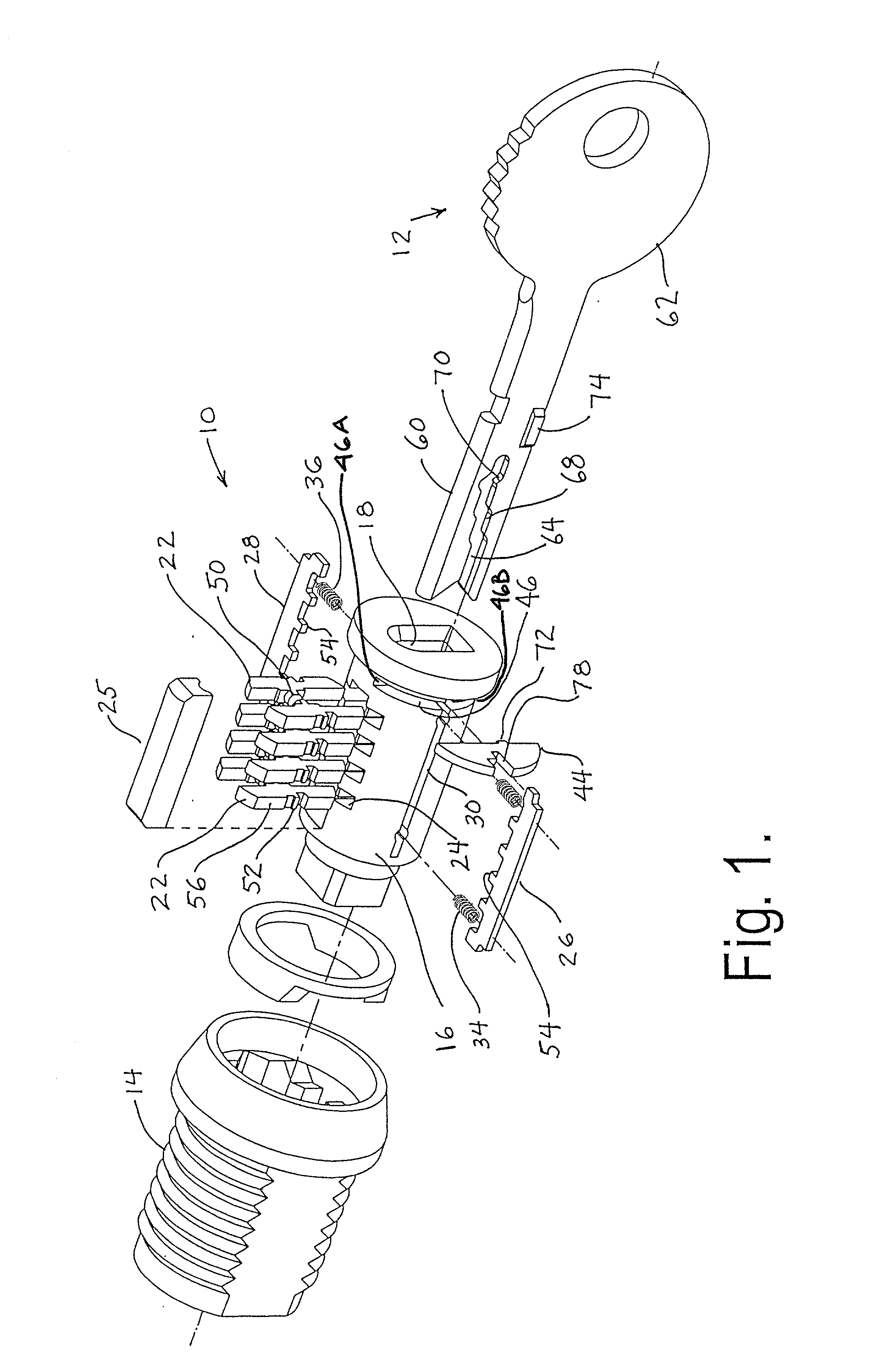
[0021] As noted above, cylinder locks which incorporate side bars are well-known in the art and the operation thereof will, accordingly, not be discussed in detail herein. Referring to the drawings, a lock which includes a pair of side bars is indicated generally at 10 in FIG. 1. The lock 10 and a properly coded key therefor, as indicated generally at 12, define a lock system. Lock 10 includes a shell 14. Shell 14 defines a cylindrical chamber which receives a rotatable plug or core 16. The keyway 18 of lock 10 is formed in core 16. Keyway 18 has a pair of opposite sides which define, therebetween, a central plane 20 (see, for example, FIG. 3). A plurality of tumblers 22 are located, for reciprocal movement in planes oriented generally parallel to the center plane 20 of the keyway, in slots 24 provided in core 16. Slots 24, in the FIG. 1 embodiment, communicate with the opposite sides of keyway 18. The tumblers 22 are captured in the slots 24, such that reciprocal motion can be impa...


PUM


Abstract

A side bar type cylinder lock includes a locking segment which is movable relative to the side bar and lock shell only in response to insertion of a key blade having a uniquely configured and located camming projection into the keyway. The locking segment movement is independent of lock tumbler movement and is required to permit side bar disengagement from the lock shell.

Description

[0001] This application is a Continuation of U.S. application Ser. No. 09 / 388,574, filed Sep. 1, 1999, and claims the benefit thereof under 35 USC .sctn.120.[0002] 1. Field of the Invention[0003] The present invention relates to cylinder locks and, particularly, to cylinder locks which incorporate side bars to enhance mechanical strength and thereby improve the ability to resist defeat through the application of torque to the cylinder. Specifically, this invention relates to enhancing the security afforded by side bar type cylinder locks by increasing the number of possible key combinations of such locks while simultaneously reducing the possibility of manufacture of key blanks which may be cut to form unauthorized keys for such locks. Accordingly, the general objects of the present invention are to provide novel and improved articles and methods of such character.[0004] 2. Description of the Prior Art[0005] Cylinder locks which employ side bars are well-known in the art. Early exam...

Claims


Application Information

Patent Timeline
IPC IPC(8): E05B27/00E05B29/00E05B29/10
CPCE05B27/0042E05B29/0066E05B27/0082Y10T70/7881Y10T70/7616
Inventor THERIAULT, KENNETH T.EDEN, CHARLES W. JR.
Owner INT SECURITY PROD
Why Eureka
Try Eureka