Support for a motion sensor of coins supplied by the hopper of a recreational machine

a technology of motion sensor and hopper, which is applied in the direction of coin dispensers, coin counters, instruments, etc., can solve the problems of difficulty in a conventional hopper

Inactive Publication Date: 2002-05-23
PROINDUMAR
View PDF0 Cites 3 Cited by
  • Summary
  • Abstract
  • Description
  • Claims
  • Application Information

AI Technical Summary

Benefits of technology

0003] The object of the invention is to allow the physical independence of the coin motion sensor fro...

Problems solved by technology

On one hand the hopper must be conceived and structured in order to allow the implantation of the mentioned optical sensor, and thus the complia...

Method used


Image

  • Support for a motion sensor of coins supplied by the hopper of a recreational machine
  • Support for a motion sensor of coins supplied by the hopper of a recreational machine

Examples


Embodiment Construction

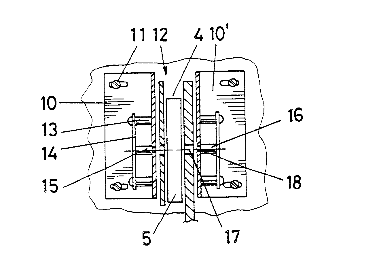
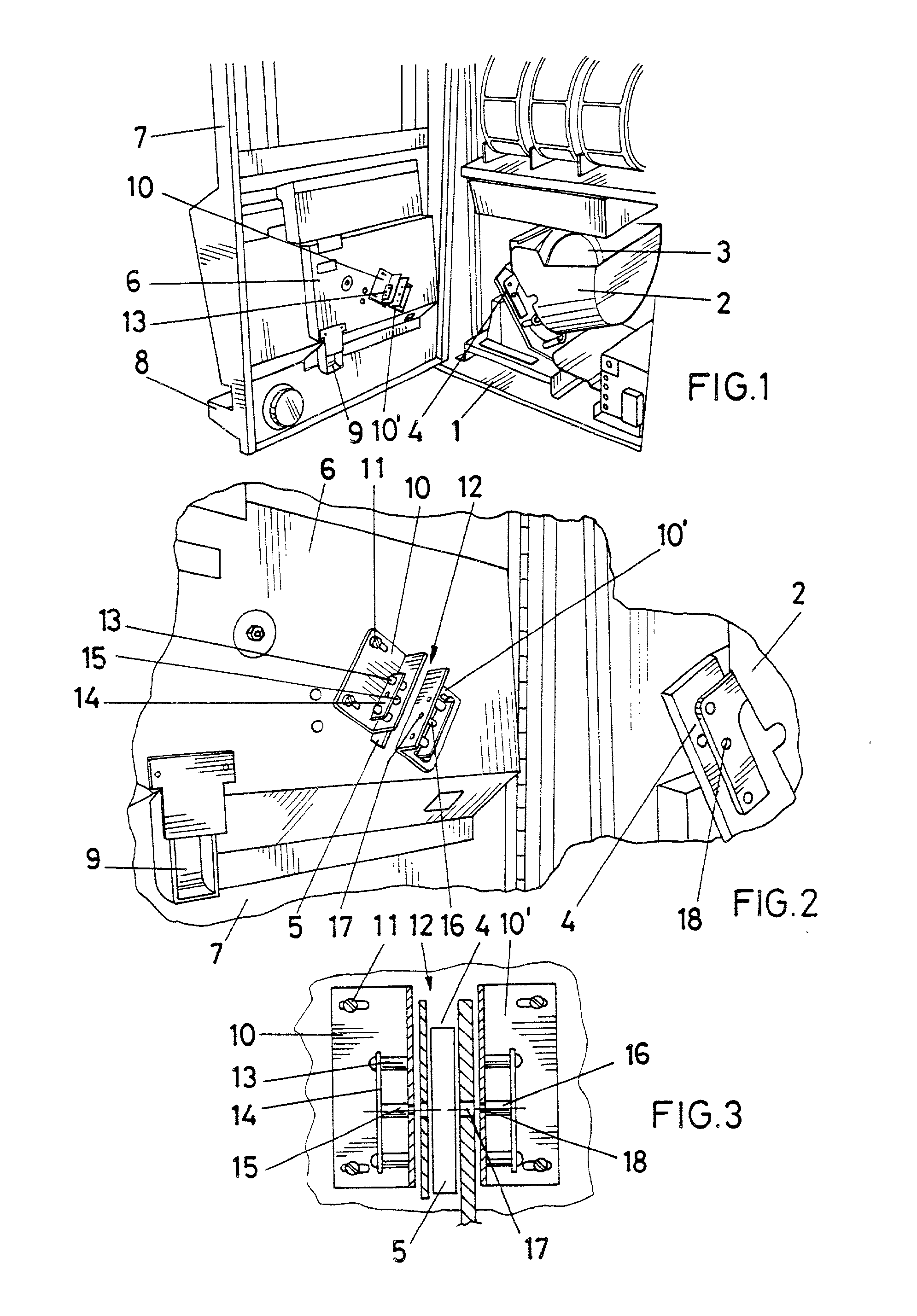
[0012] The support that the invention proposes has been conceived to resolve in a completely satisfactory way the previously expressed problems, in both of the mentioned aspects, so that on one hand the optical sensor is not located in the hopper itself, which allows the use of any conventional hopper with a single control point over the coins, and on the other hand, due to the special arrangement of said support in the context of the machine, it can be thoroughly guaranteed that the second control of the coin is performed when it does not have any other option than reaching the prize collection tray.

[0013] To accomplish this, more specifically, said support is arranged on the inner door panel of the machine, surrounding specifically the classical groove which, when facing the hopper, pours directly into the coin collection tray, so that, as previously pointed out, when the coin reaches said groove when passing through the optical sensor, its drop into the collection tray is ensured...


PUM


Abstract

Especially designed as an opto-electronic sensor, as an addition to the classic electromechanical sensor available in games machine dispensers (2) awarding prizes in cash, consisting of a pair of bent plates (11) jointly fixed to the entrance door (6) of the machine door (7), specifically framing the slot (5) in the entrance door (6), for the transport of coins from the dispenser (2) to the applicable prize-collecting tray (6), so that the parallel branches of these plates (10-10') support the photoemitter (15) and photoreceptor (16) respectively in this opto-electronic sensor, interconnected through orifices (17) in the plates themselves (10-10') and in the orifices (18) that are operated at the front of the dispenser (2), framing the exit coin mouth (4), so that this luminous beam is interrupted during coin movement to apply the necessary detection and accounting.

Description

SUMMARY[0001] Especially conceived for an electronic eye sensor, complementary of the classical electromechanical sensor contained in the hoppers (2) of recreational machines which dispense cash prizes, consisting of a pair of angular brackets (11) which attach solidly to the inner door panel (6) of the machine's door (7), specifically surrounding the groove (5) that exists on said inner door panel (6) for the coins to pass from the hopper (2) to the corresponding collection tray (8), in order that the parallel flanges of said pieces (10-10') respectively support the photo-emitter (15) and the photo-receptor (16) of said electronic-eye sensor, communicated with each other by means of openings (17) on the brackets (10-10') themselves and of openings (18) made in the front area of the hopper (2), surrounding the coin outlet (4), so that said ray of light is interrupted when each coin passes through in order to attain the required detection and consequent counting.OBJECT OF THE INVENTI...

Claims


Application Information

Patent Timeline
IPC IPC(8): G07D1/00G07D9/04
CPCG07D1/00G07D9/04
Inventor FRANCO MUNOZ, JESUS
Owner PROINDUMAR
Why Eureka
Try Eureka