Retaining wall masonry block

a masonry block and retaining wall technology, applied in the field of masonry blocks, can solve the problems of difficult lifting, carrying and placing, and the type wall would not be as strong, and the pressure of the solid concrete wall cannot be the same,

Inactive Publication Date: 2002-07-04
MATT STONE
View PDF0 Cites 58 Cited by
  • Summary
  • Abstract
  • Description
  • Claims
  • Application Information

AI Technical Summary

Problems solved by technology

Often during construction of homes, buildings, bridges or other residential and commercial structures, the existing soil levels must be cut vertically or to sharp slopes which cannot be naturally maintained.
The same wall could be constructed of concrete block that is cemented in place; however, this type wall would not be as strong and could not withstand the same pressures as the solid concrete wall.
Retaining wall blocks must be heavy to accomplish their purpose, and are therefore difficult to lift, carry and place in the selected location.
In order to carry the blocks it is necessary to place the fingers underneath the blocks, which means the block must be

Method used


Image

  • Retaining wall masonry block
  • Retaining wall masonry block
  • Retaining wall masonry block

Examples


third embodiment

[0035] In a third embodiment, illustrated in FIG. 7, the centerline A' of the second cavity 238 of the body 212 extends inwardly from the side 218 and angles toward the back face 216. The angle B', between the centerline A' and a portion of the side 218 that is adjacent to the second opening 236 is less than 90 degrees. In this embodiment, the first cavity 228 remains as a mirror image of the second cavity 238.
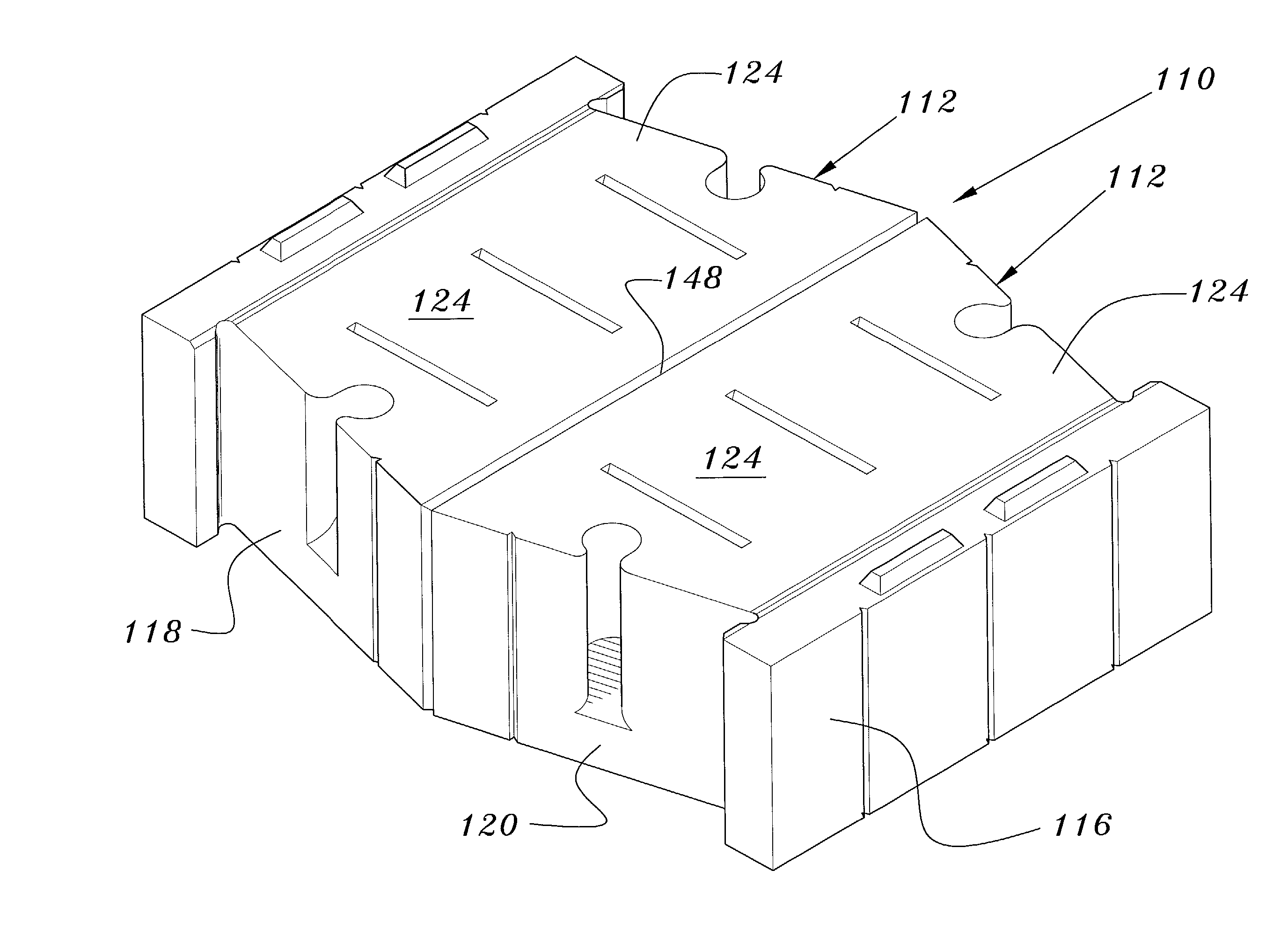
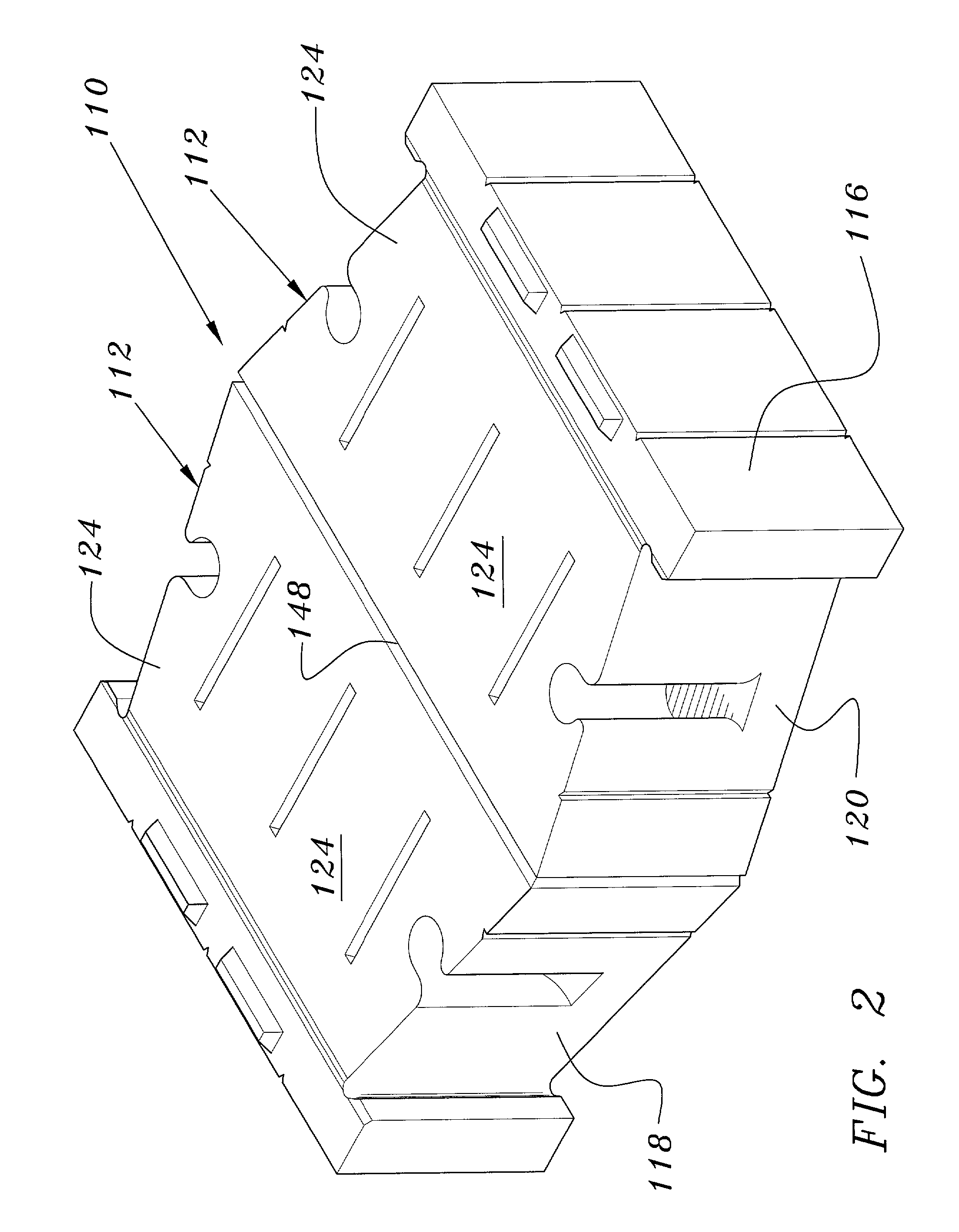
embodiment 110

[0036] As can be seen in FIG. 6, the bottom face 24 of the body 12 has a plurality of grooves formed therein. There is a least one groove 40 extending along a portion of the bottom face 24 generally perpendicular to the front face 14 and perpendicular to the back face 16. In the embodiment illustrated there are three such grooves spaced apart from one another. There is also a groove 42 extending along the bottom face 24 that is generally parallel with and proximal to the back face 16. As seen in FIG. 4 and FIG. 5, a groove 44 is formed in side wall 18 and side wall 20, which is proximal the front face 14 and parallel thereto. As seen in FIG. 6 and FIG. 10, at least one groove 46 is formed in the back face 16. In a preferred embodiment, this groove lies in the same plane as a corresponding groove 40 in the bottom face 24. Also, in a preferred embodiment, as illustrated, there are three grooves 46, each lying in a plane with a corresponding groove 40 in the bottom face 24. In the embo...


PUM


Abstract

A masonry block that may be used in construction of block walls particularly retaining walls for retaining soil and preventing soil erosion. A masonry block having at least one body with a front face, back face, a pair of sides extending therebetween a top face and a bottom face, defining a block having six major surfaces. One of the sides has an opening therethrough that is in communication with a cavity extending inwardly in relation to the body. The cavity is sized and configured to receive at least a portion of a hand therein to provide structure for easily grasping and lifting the block. The centerline of the cavity extends from the opening inwardly so that the angle between the centerline and the portion of the side adjacent to the opening is less than 90 degrees, so that the cupped fingers of a user may be received therein.

Description

[0001] 1. Field of the Invention[0002] The current invention relates generally to masonry blocks that may be used in construction of block walls. These masonry blocks are particularly useful for constructing retaining walls for retaining soil and preventing soil erosion.[0003] 2. Description of the Prior Art[0004] Masonry blocks that are used to construct walls are well-known for both commercial and residential construction. Often during construction of homes, buildings, bridges or other residential and commercial structures, the existing soil levels must be cut vertically or to sharp slopes which cannot be naturally maintained. Varied structural elements have been used to construct retaining walls to retain the soil therebehind and thus prevent erosion.[0005] The strength of the retaining walls depends upon the height of the soil cut, the slope of the cut and the type of soil being retained, whether sandy, loam or clay. Certainly walls of solid concrete with extensive footers and d...

Claims


Application Information

Patent Timeline
IPC IPC(8): E02D29/02E04B2/02E04C1/39
CPCE02D29/025E04B2002/0258E04B2002/026E04C1/395
Inventor MATTOX, JEFFREY A.DEAN, JEFFREY M.WILLIAMS, JEFFREY S.
Owner MATT STONE
Why Eureka
Try Eureka