
Trunk mountable equipment rack

Inactive Publication Date: 2002-08-29
VIGOR SPORTS
View PDF0 Cites 56 Cited by
  • Summary
  • Abstract
  • Description
  • Claims
  • Application Information

AI Technical Summary

Benefits of technology

[0007] Particular embodiments of the invention also include a plurality of strap housing assemblies coupled to the legs that have retractable straps capable of securing the mountable equipment rack to a vehicle. Each strap housing assembly includes a cover, a retractable strap and a securing mechanism. Each retractable strap can be pulled out to couple a leg to the trunk of a vehicle and retracted back into the strap housing assembly. Therefore, the mountable equipment rack is easily placed onto and removable from a trunk of a vehicle.

Problems solved by technology

However, the angles created by repositioning the structures are limited, and the removability of the structures creates a potentially cumbersome apparatus that hinders quick and easy handling.
Furthermore, there is no centralized frame around which all structural and support components move.

Method used


Image

  • Trunk mountable equipment rack
  • Trunk mountable equipment rack
  • Trunk mountable equipment rack

Examples


Embodiment Construction

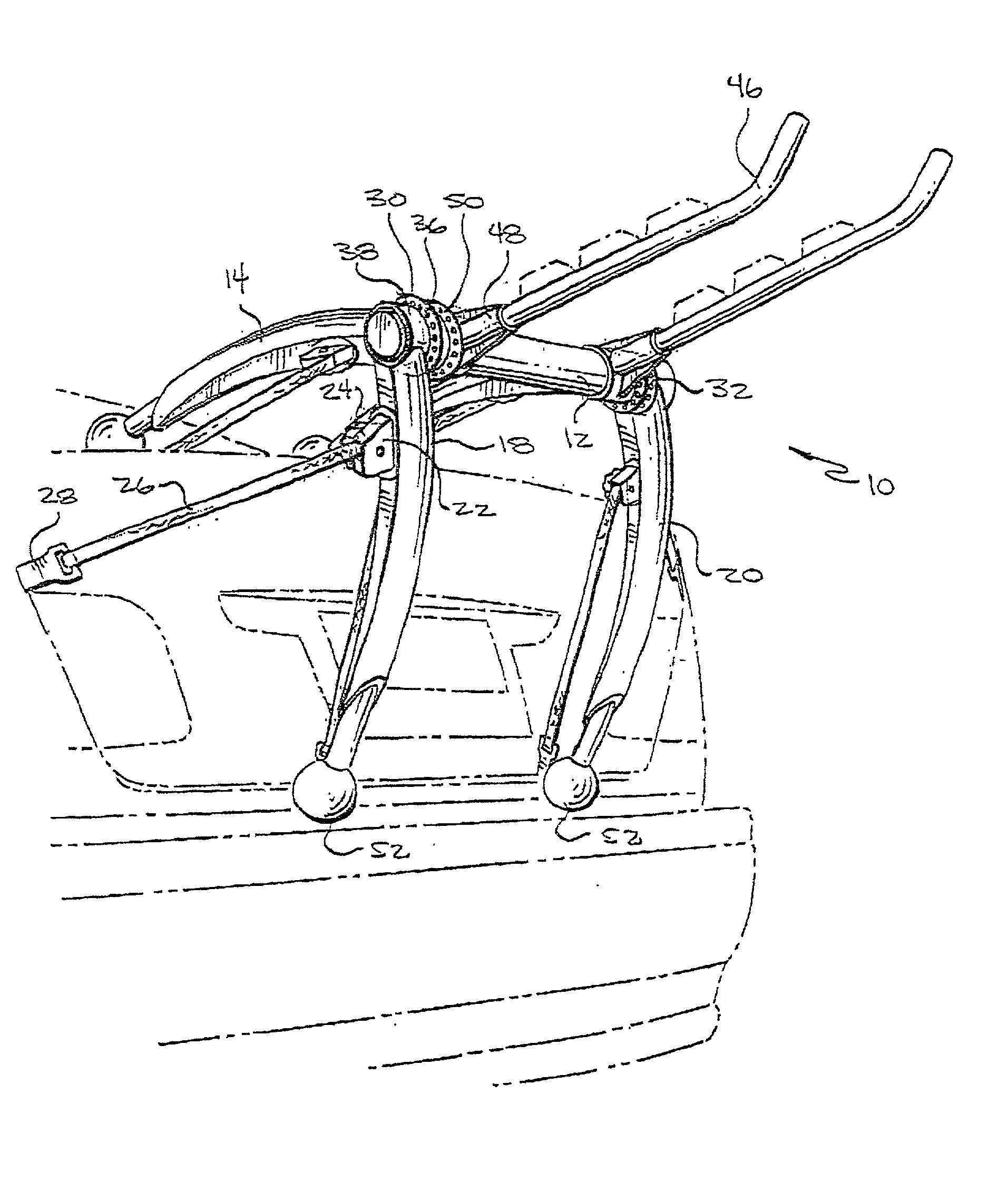
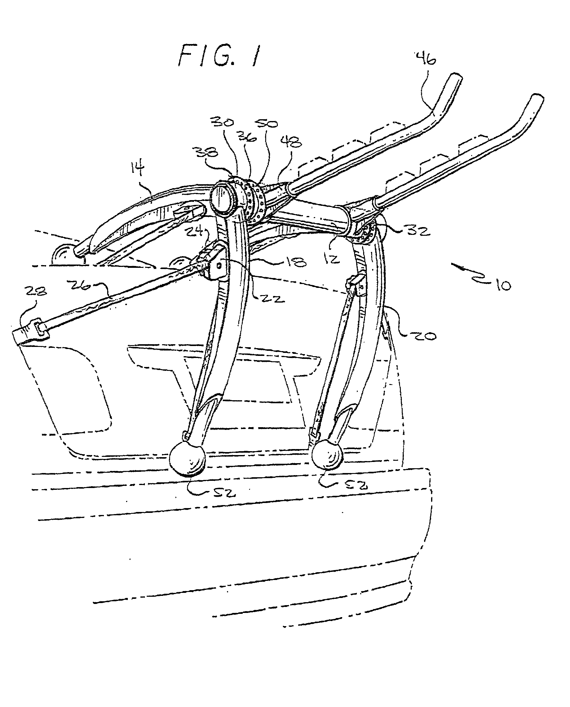
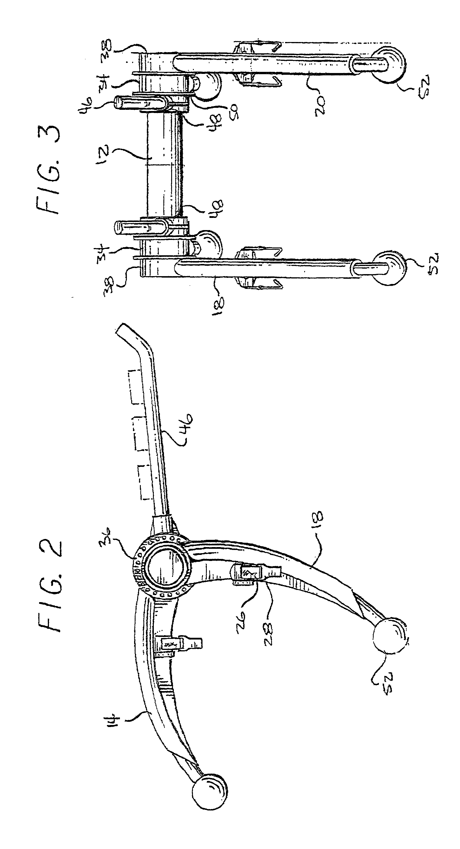
[0019] FIG. 1 shows a mountable equipment rack 10 having a cross member 12 disposed between a plurality of arcuately oriented legs, secured to the trunk of a vehicle. The plurality of legs includes a first rear leg 14, a second rear leg 16, a first front leg 18, and a second front leg 20. Although the legs are shown as arcuately shaped in FIG. 1, they may be straight or curved, and additionally the legs do not all need to be of the same shape. Each leg is coupled at one end to the cross member 12. The mountable equipment rack 10 also includes at least one strap housing assembly 22. Each strap housing assembly 22 includes a cover 24, a retractable strap 26 and a securing piece 28. As shown in FIG. 1, each retractable strap 26 is extended so that the securing piece 28 attached to each retractable strap 26 releasably secures the mountable equipment rack 10 to a part of the trunk of the vehicle. Each strap housing assembly 22 may also include a knob that can be turned to facilitate the ...


PUM


Abstract

A trunk-mountable equipment rack includes a frame having a cross member and a plurality of legs. The legs have straps attached that are capable of extending to couple the legs to the trunk of a vehicle. These straps allow the equipment rack to be placed on and secured to different sizes and shapes of trunks of vehicles. The invention also includes support bars for securing equipment to the equipment rack for transportation on a vehicle.

Description

[0001] 1. Field of the Invention[0002] The present invention relates generally to equipment racks. Specifically, the invention relates to equipment racks that are adjustable and capable of holding sports equipment such as bicycles and skis, and that also mount and secure to vehicles for transportation.[0003] 2. General Background and State of the Art[0004] There are many prior art equipment racks that mount on vehicles for the transportation of sports equipment and other articles. One such equipment rack, disclosed in U.S. Pat. No. 5,495,970, includes several structures removably mounted around a shaft. These structures are removable from the shaft and replaceable to create different angular positions relative to the shaft. However, the angles created by repositioning the structures are limited, and the removability of the structures creates a potentially cumbersome apparatus that hinders quick and easy handling.[0005] Another prior art equipment rack, disclosed in U.S. Pat. No. 5,2...

Claims


Application Information

Patent Timeline
IPC IPC(8): B60R9/06B60R9/10
CPCB60R9/06B60R9/10
Inventor JEONG, CHANYOUNG
Owner VIGOR SPORTS
Learn More