Portable changeable illuminated display for vehicles and other miscellaneous purposes

a technology for changing lights and illuminated displays, which is applied to illuminated signs, displays, boards, etc., can solve the problems of requiring large amounts of current draw and significant maintenance, lack of portability enabling them to be removed, and more limited use, so as to facilitate and quick exchange, prevent damage from impact, and easy to remove and reposition

Inactive Publication Date: 2009-04-02
VANDERGRIFF JON +1
View PDF30 Cites 28 Cited by
  • Summary
  • Abstract
  • Description
  • Claims
  • Application Information

AI Technical Summary

Benefits of technology

[0034]To enable the easy and quick exchange of graphic media, the mountable signage enclosure may further comprise a flexible flap on the back side for providing access to the encasement through which the graphic media is inserted, the flap being biased in the closed position by an attachment means sealing the flap to the back side of the mountable signage enclosure.
[0035]This invention addresses all of the above concerns by offering a single molded frame with support mechanism attached to allow it to stand independent of any mounting hardware. The support mechanism allows the frame to mount on the inside or outside of an automobile window and accessories allow it to sit on a horizontal surface or stand independently supported on an extendable stake for yards. The frame is embedded with LED's contained within from the circumference lighting the inserted media within the shape of an aerodynamically efficient oval shape for directing air flow around the perimeter and over the surface. The oval frame is secured to the side of an automobile using strong suction cups that are easily removable and repositionable to alternative smooth surfaces such as glass windows, metal, Formica, plastic, etc. Two suction cups are able to be re-positioned in either direction to allow for internal and external mounting of the oval frame inside on car windows or on the sides of vehicle doors and frames.
[0036]In addition, the frame offers an opening in the center allowing smaller oval shaped plastic inserts containing messages, fiber optic or EL signs, and other accessory inserts that repel moisture and keep the internal paper, vinyl, or other printed material from becoming wet.
[0037]The cavity displaying alphanumeric characters and / or graphic sheets is large enough to insert a standard sheet of printed paper from a computer printer allowing consumers to design and print their own special graphics, messages, or company logos for display. The cavity is designed to also accommodate a thicker material insert such as fabric embroideries or even self-contained EL or fiber optic panels to display additional lighted messages with internal power supplies through the clear flexible vinyl window provided on the insert.
[0038]In addition, the frame contains a rechargeable battery pack that is continuously charged by a photovoltaic cell array protected by a clear coated epoxy-like substance to prevent damage from impact thus eliminating the necessity of changing batteries although a replaceable battery system falls under the intended embodiment of this invention as well.

Problems solved by technology

Hundreds of different configurations of illuminated signs exist in the market with as many uses, many requiring large amounts of current draw and significant maintenance.
However, all seem to lack the portability enabling them to be removed and repositioned easily, allowing them to be applied or attached to various surfaces with ease and also have the ability to change alphanumeric characters and graphics with equal ease.
Others, being more limited in usage, are designed to be mounted on one particular product with a mounting configuration that prevents them from being mounted on any other product or object.
These applications are intended for a single purpose and not designed to be removed and positioned elsewhere easily, due to the difficulty of removal and the marring and gumming of the window surface due to the removal of the adhesive tape.
However, the enclosure designs prohibit these signs from being applied to the surface of vehicles due to their inherent problems with wind resistance.
Flashing or blinking applications would not be applicable to vehicle signs due to safety concerns, such as the potentially dangerous distraction of neighboring drivers or laws prohibiting the flashing of particular colors.
Yet other signs offering energy saving options either rely on fluorescent tubes requiring power from outlets, such as U.S. Pat. No. 4,937,499 to Hunte and U.S. Pat. No. 4,989,956 to Wu, or are too bulky and use breakable materials such as glass tubes which offer too much wind resistance and potential breakage, qualities that are unsuitable for application to a vehicle.
This arrangement would add unnecessarily to the weight and bulkiness; and thick plastic elements that could shatter upon impact with other vehicles or the roadway if applied to a car sign.
Prior art signage using incandescent, fluorescent signs, and signs using a multitude of LED's, such as shown in U.S. Pat. No. 7,217,012 to Southard where wires connect a series of LED's to form letters and graphics, all require excessive currents and voltages to attach to the sides of moving vehicles, are far too heavy and bulky offering tremendous wind resistance and potential danger of dislodging causing an accident, and are not conducive to easily changing the message once the wires, LED's and mounting hardware are in position.
Even signs that employ LED's to illuminate them are far too large and bulky, and present no easy way of mounting them to the side of a vehicle.
Popovich shows a cylindrical enclosure projecting light along a longitudinal axis to any sign; but offers no method of interchangeability or mounting methods to adhere the unit to a moving vehicle.
This arrangement would prove to be dangerous and unwieldy, due to the possibility of crimping the wiring and creating a short circuit.
They do not have the ability to easily create, change, or modify the messages, nor can they apply photographic signs, nor can they illuminate fabric embroideries or support additional lighted inserts.
However, the supporting structures are far too large to apply to a vehicle surface and are intended for applications outside of the use intended for vehicles.
Many existing signs are attached to the sides of vehicles using adhesives and do not offer the ability to change messages quickly.

Method used


Image

  • Portable changeable illuminated display for vehicles and other miscellaneous purposes
  • Portable changeable illuminated display for vehicles and other miscellaneous purposes
  • Portable changeable illuminated display for vehicles and other miscellaneous purposes

Examples


Embodiment Construction

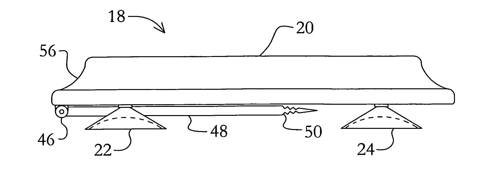
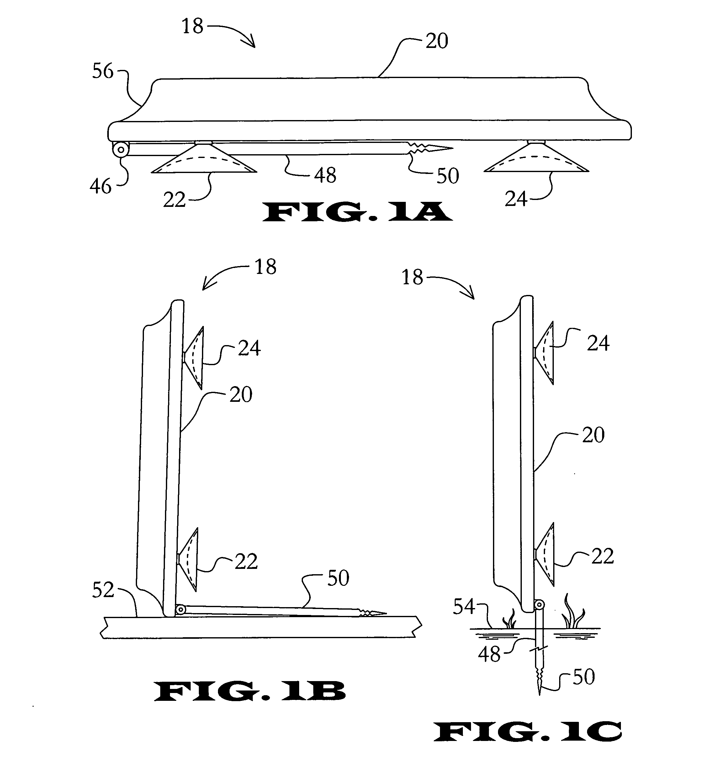
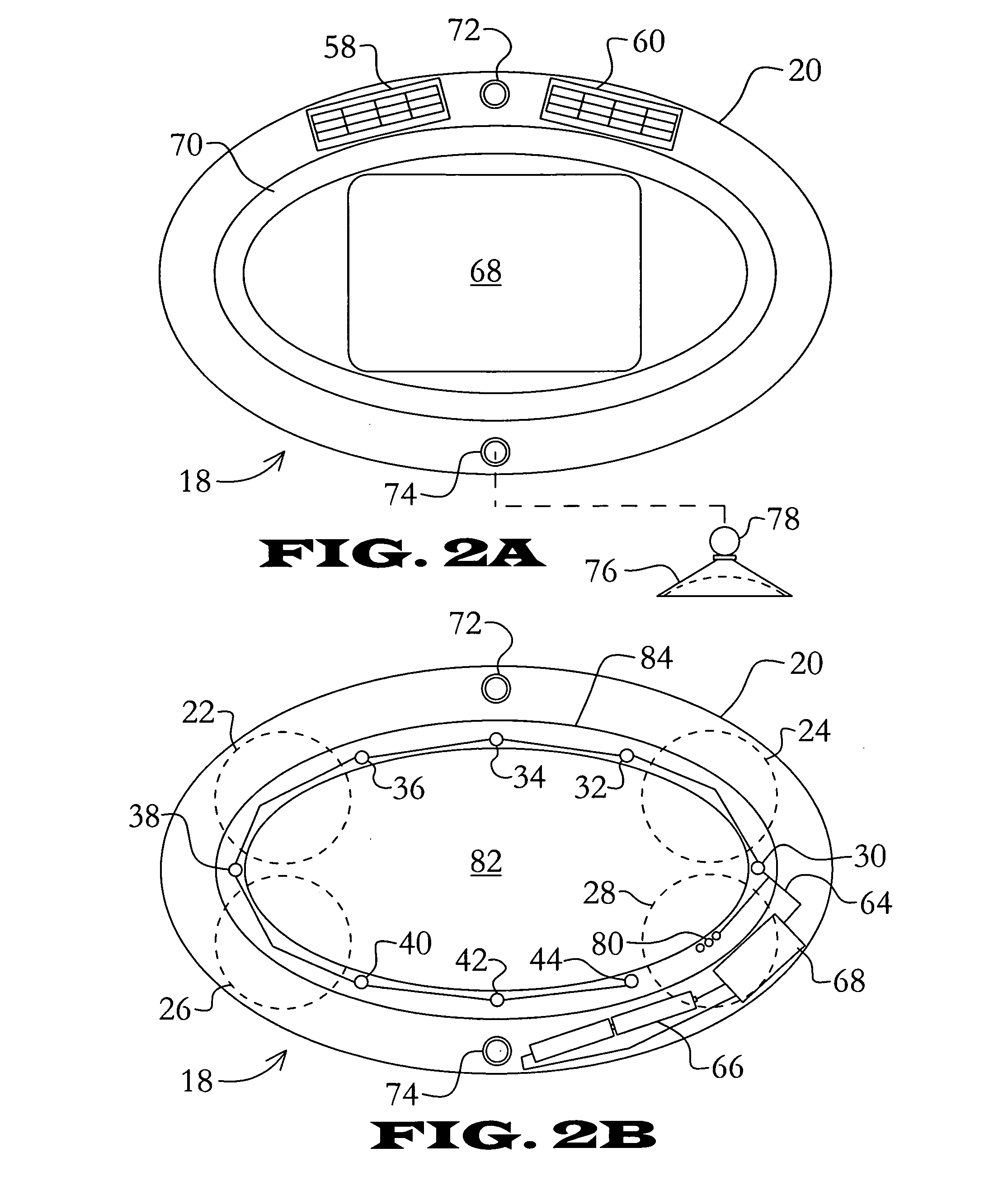
[0049]mountable signage enclosure 18[0050]molded frame 20[0051]suction cup 22, 24, 26, 28[0052]LED 30, 32, 34, 36, 38, 40, 42, 44[0053]hinge 46[0054]support arm 48[0055]pointed stake 50[0056]surface 52[0057]ground 54[0058]aerodynamic beveling 56[0059]photovoltaic cell 58, 60[0060]switching circuit 62[0061]wire 64[0062]battery 66[0063]plastic window 68[0064]insert 70[0065]attachment socket 72, 74[0066]detachable suction cup 76[0067]stud 78[0068]contacts 80[0069]encasement 82[0070]lip 84[0071]powered sign 85[0072]fabric material 86[0073]graphic 87[0074]plastic optical fibers 88, 90, 92[0075]bundle 94[0076]LED 96[0077]substrate 98[0078]wire 100[0079]jack 102[0080]EL display 104[0081]PCB 106[0082]plastic surface 108[0083]substrate 110[0084]magnet 112, 114, 116[0085]rail 118, 120[0086]jack 122[0087]flexible covering 124[0088]metallic surface 126[0089]stake 128[0090]locking tab 130[0091]extension arm 132[0092]hole 134[0093]mount 136[0094]stud 138, 140[0095]extension 142[0096]rear 144

[0097...


PUM


Abstract

A mountable signage enclosure for encasing a graphic media comprising a frame being generally elliptic or having a substantially aerodynamic edge, an encasement for protectively displaying the graphic media through a clear covering through a front side of the mountable signage enclosure and allowing the exchange of the graphic media, a plurality of light emitting diodes perimetrically positioned to illuminate the encasement and the graphic media inserted therein, a power source for providing power to the light emitting diodes, a plurality of suction cups fixed to a back side of the mountable signage enclosure enabling the fixing of the mountable signage enclosure on a smooth surface; and optionally comprising a photovoltaic charging means providing an electric current for charging the power source. The mountable signage enclosure provides a stand-alone illuminated sign that can be easily installed in a variety of configurations, while allowing the quick exchange of the signage.

Description

RELATED APPLICATION DATA[0001]This application claims the benefit of U.S. provisional application Ser. No. 60 / 995,842 filed Oct. 1, 2007.BACKGROUND OF THE INVENTION[0002]1. Field of the Invention[0003]The present invention relates to portable and attachable signage, and more particularly to illuminated signage with replaceable displays.[0004]2. Description of the Related Art[0005]There has risen a strong need to not only conserve energy in the growing world economies, but also to meet the demand for supplying more energy for the advertising and signage industries. It would then, seem as no surprise that a constant search for more energy efficient signage is ongoing. Hundreds of different configurations of illuminated signs exist in the market with as many uses, many requiring large amounts of current draw and significant maintenance. However, all seem to lack the portability enabling them to be removed and repositioned easily, allowing them to be applied or attached to various surfa...

Claims


Application Information

Patent Timeline
Patent Type & Authority Applications(United States)
IPC IPC(8): G09F13/18G09F15/00
CPCG09F15/00G09F13/18
Inventor VANDERGRIFF, JONWAINWRIGHT, HARRY L.
Owner VANDERGRIFF JON
Why Eureka
Try Eureka