

Precision abrasive finishing apparatus
a technology of abrasive finishing and precision, which is applied in the direction of gear teeth, gear teeth, gear machine, etc., can solve the problems of abrasive slurries that require periodic replacement, flat base surface as well as work pieces, and need periodic re-truing of the base, so as to achieve a lower cost and work
- Summary
- Abstract
- Description
- Claims
- Application Information
AI Technical Summary
Benefits of technology
Problems solved by technology
Method used
Image

Examples
example 1
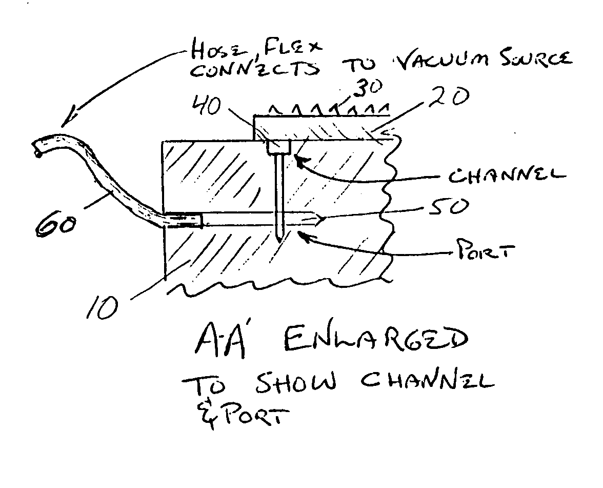
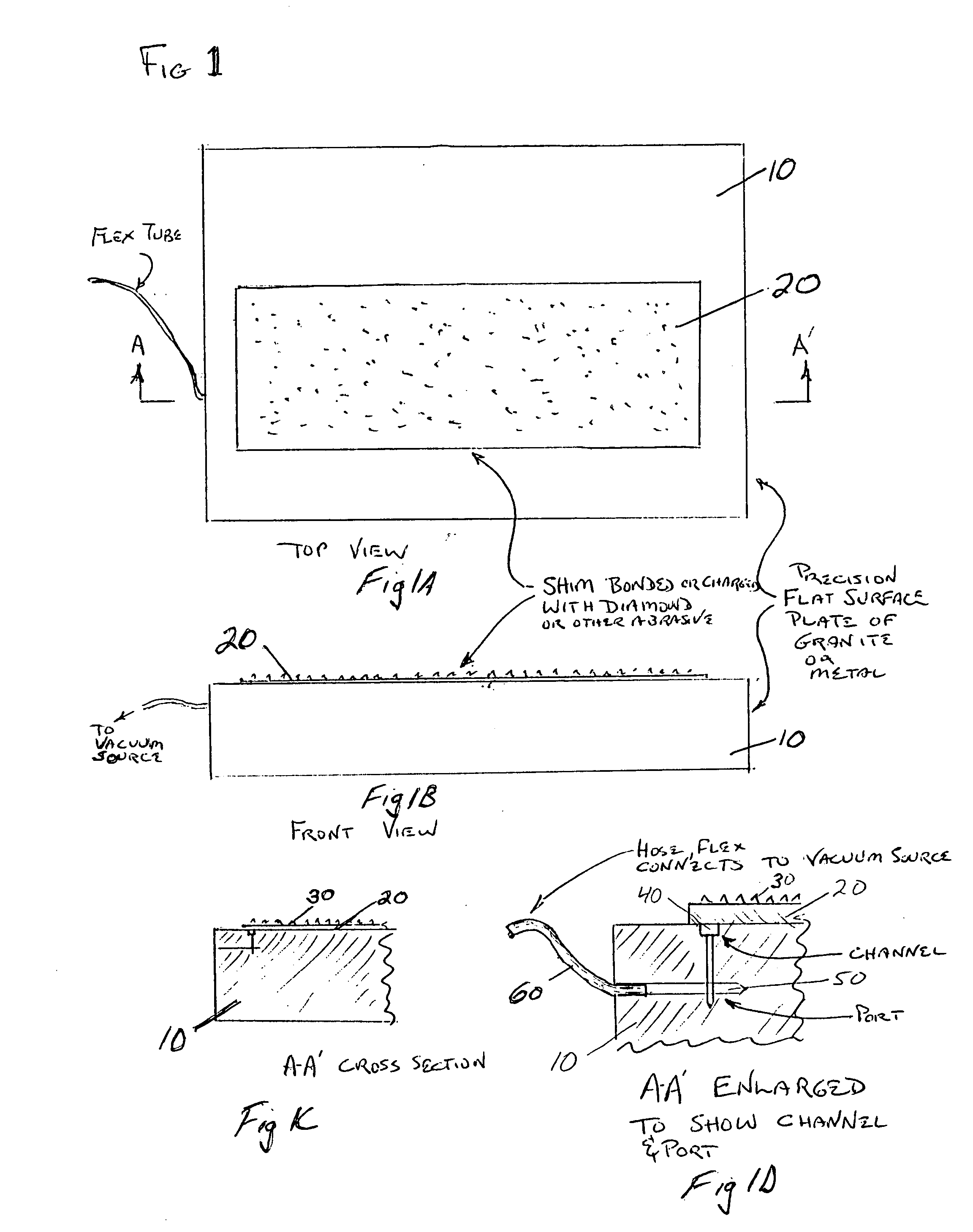
[0048] A 6″×18″×0.012″ thick sheet of steel shim was vacuum clamped to ground-flat aluminum jig-plate of similar area by milling a 0.006″ deep×0.020″ wide channel loop into the jig-plate just within the footprint of the shim's perimeter. This channel loop was in fluid communication with the exterior of the jig-plate by means of an intersection bore into the inch thick jig-plate. A plastic tube was fitted to the portion of the bore that exited from the jig-plate and then connected to a vacuum pump. Clamping was quickly achieved by activating the pump and manually pressing down on the shim to close off gaps between the shim and jig plate sufficiently until evacuation and equilibrium partial vacuum resulted. The holding power of the vacuum clamp was sufficient for the steel shim to resist lapping forces horizontal to the surface and remain in place over the channel loop.
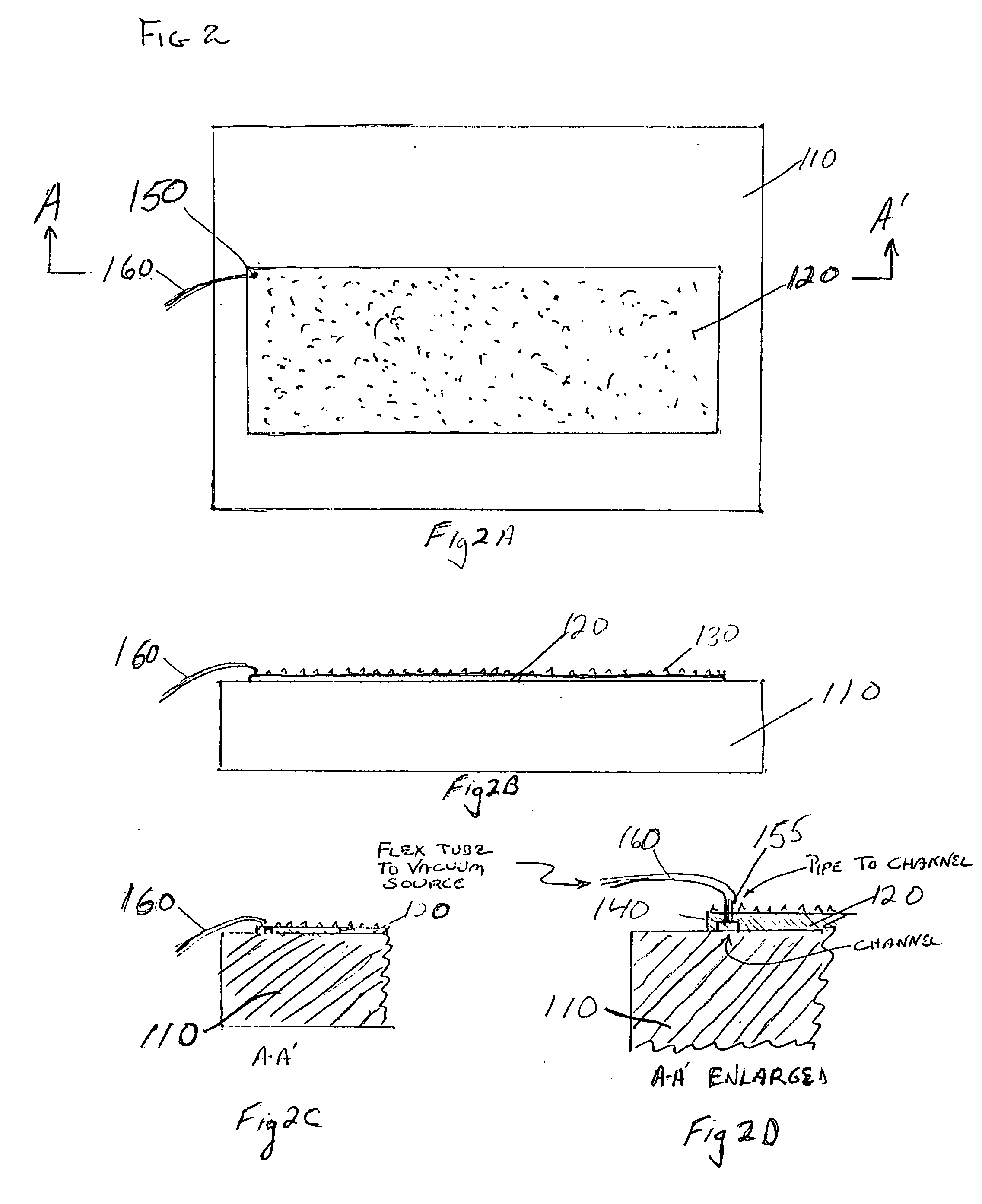
[0049] An second embodiment, shown in FIGS. 2A-2D, may be used to retrofit existing lapping surface plates to permit...
example 2
[0053] A 6″×18″×0.012″ thick sheet of steel shim has been vacuum attached to an existing granite surface plate of larger area using 5⅝″×17⅝″×0.125″ thick spacer of precision-ground stock having a 0.125″ wide×0.035″ deep channel section cut 0.070″ in from the perimeter of each side of the granite surface plate. A perimeter seal of common (sponge) elastomeric weather strip material was placed about the perimeter. The opposing channels were ported together and to a plastic tube that connected to the vacuum pump.
[0054] A fourth embodiment, shown in FIGS. 5A-5C, contemplates use of multiple abrasive shims 520-520n. The purpose of using multiple shims is to extend the size of the lapping surface beyond the size restrictions of conventionally available shim stock and ground stock. Thus, apparatus of the present invention used in conjunction with conventional lapping tables may enable the user to employ nearly, the entire surface, if not all, of the lapping table, as with conventional lapp...
PUM
| Property | Measurement | Unit |
|---|---|---|
| perimeter | aaaaa | aaaaa |
| abrasive | aaaaa | aaaaa |
| flatness | aaaaa | aaaaa |
Abstract
Description
Claims
Application Information