Tubing holding device for roller pumps

Inactive Publication Date: 2008-09-04
MEDTRONIC INC
View PDF7 Cites 27 Cited by
  • Summary
  • Abstract
  • Description
  • Claims
  • Application Information

AI Technical Summary

Benefits of technology

[0007]The present invention overcomes the shortcomings of the prior art with respect to tubing holding devices for roller pumps by providing tubing holding devices that are easily removable from roller pumps, allowing for easy exchange of tubing holding devices of different tubing sizes. Additionally, the tubing holding devices can be partially removed and opened so that the devices do not have to be completely removed from the roller pump in order to exchange tubing of the same size. Another advantage of the tubing holding devices is that during tubing loading

Problems solved by technology

The disadvantage of using such fastening inserts is that they need to be screwe

Method used


Image

  • Tubing holding device for roller pumps
  • Tubing holding device for roller pumps
  • Tubing holding device for roller pumps

Examples


Example

[0030]With reference to the accompanying figures, wherein like components are labeled with like numerals throughout the several figures, tubing holding devices for roller pumps, roller pump designs including tubing holding devices, and methods of loading tubing in roller pumps are disclosed, taught and suggested by the multiple embodiments.

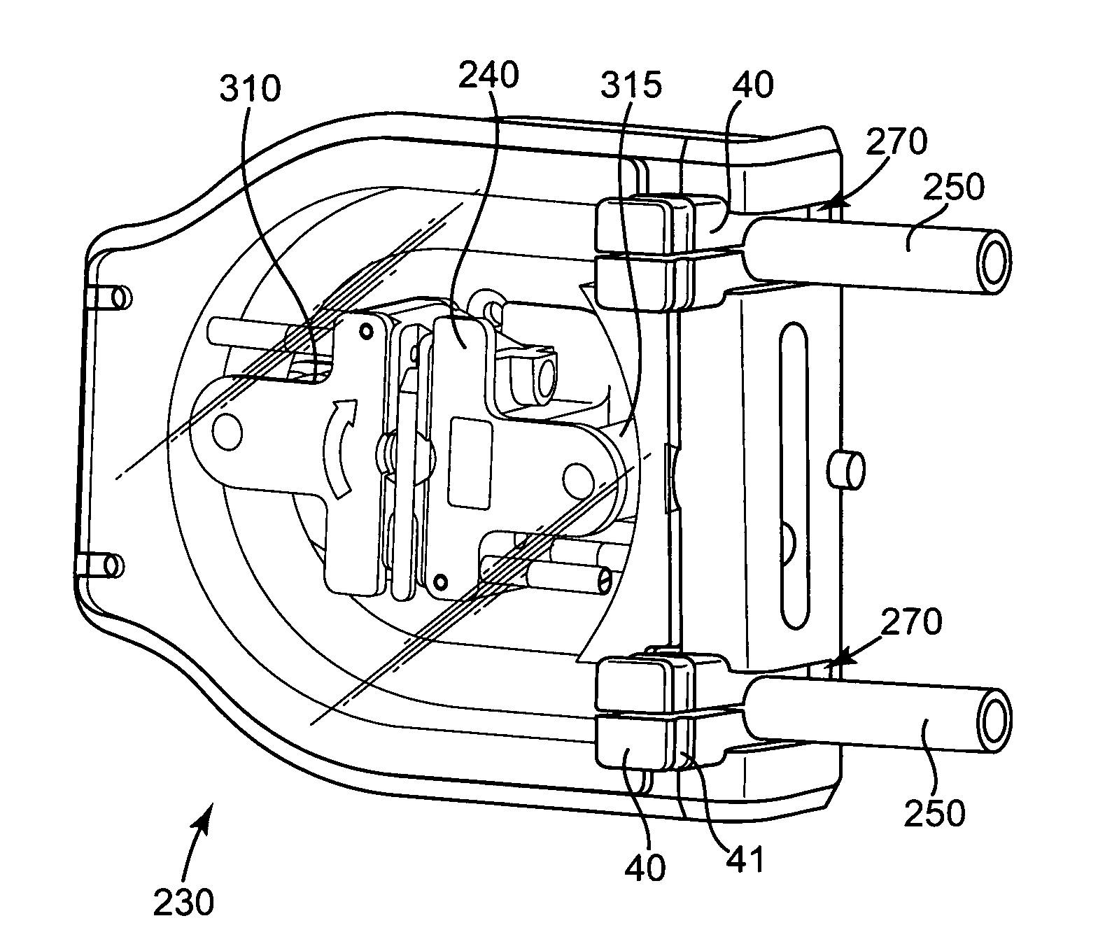
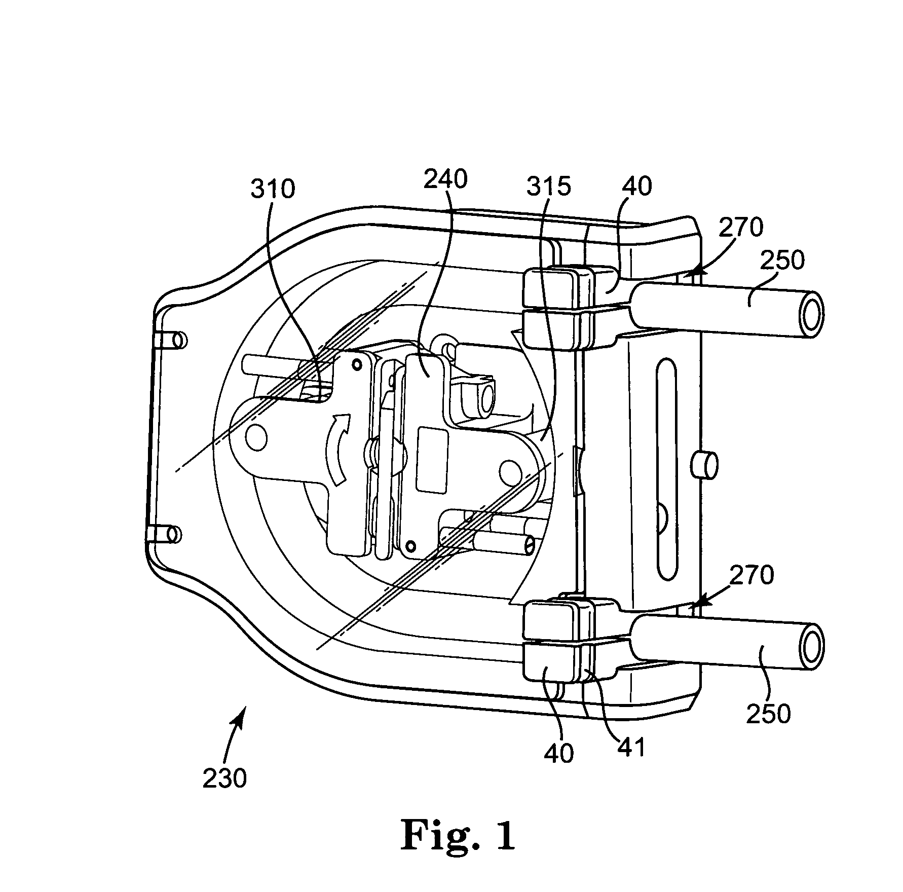
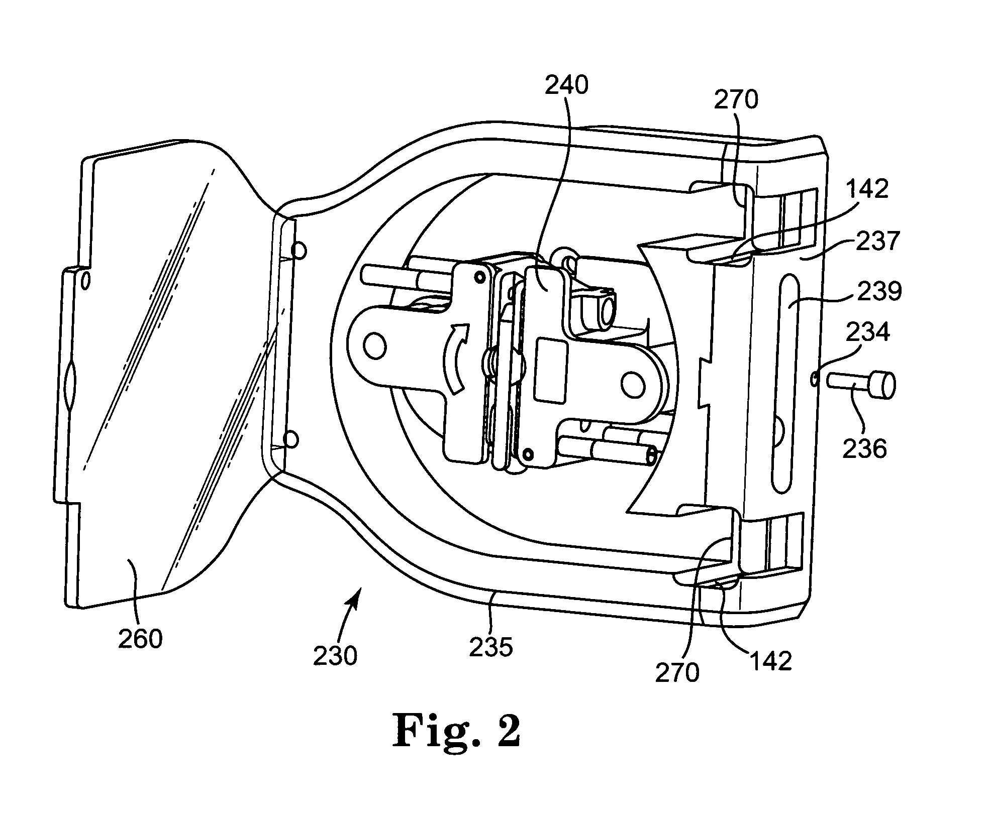
[0031]As shown in FIG. 1, a pump head 230 of a roller pump comprises a pump stator 235 and a pump rotor 240. Pump stator 235 generally comprises a hollow chamber having a surface against which one or more hoses or tubing 250 are compressed by pump rotor 240. Pump rotor 240, which is rotatable about its longitudinal axis, is arranged in pump stator 235 in such a manner that pump rotor engages hoses 250 positioned in pump stator 235 with one or more rollers (preferably with two rollers, as shown in FIG. 1 by 310 and 315). On rotation of pump rotor 240, rollers 310 and 315 compress tubing 250 as they are rolled along tubing 250. A fluid medium contai...


PUM


Abstract

A tubing holding device for a roller pump is disclosed. The tubing holding device is removable from the roller pump, slidably moveable and able to be opened to allow for easy exchange of tubing in roller pumps. The tubing holding device comprises a clamping mechanism that securely holds tubing in place. Tubing of various sizes may be used within a roller pump by selecting the appropriately sized tubing holding device, or by using a tubing holding device, such as one embodiment disclosed, which may be adjustable for different sizes of tubing. Roller pumps including the tubing holding devices, and methods of loading such roller pumps are also disclosed.

Description

CROSS REFERENCE TO RELATED APPLICATION[0001]This application claims the benefit of U.S. Provisional Application having Ser. No. 60 / 720,013, filed Sep. 23, 2005, entitled “TUBING HOLDING DEVICE FOR ROLLER PUMPS,” which application is incorporated herein by reference in its entirety.FIELD OF THE INVENTION [0002]The present invention relates to roller pumps used in medical devices or systems (e.g., heart-lung bypass machines). More particularly, the present invention relates to a tubing holding device for roller pumps that is moveable and able to be opened to allow for easy exchange of tubing in roller pumps.BACKGROUND OF THE INVENTION [0003]Roller pumps have many uses in the medical field. For example, roller pumps are used as blood pumps during hemodialysis or cardiopulmonary bypass. Generally, medical roller pumps consist of a pump head and a pump drive, with the pump head comprising a pump stator and a pump rotor. The pump stator is essentially a hollow chamber having a surface aga...

Claims


Application Information

Patent Timeline
IPC IPC(8): F04B43/12A61M60/113A61M60/279A61M60/35A61M60/462A61M60/835
CPCA61M1/1037F04B43/1253A61M1/1039F16L3/1041F16L3/1033A61M60/113A61M60/279A61M60/835A61M60/35A61M60/462
Inventor LAWRENCE, ROBERT J.CARPENTER, WALT L.
Owner MEDTRONIC INC
Why Eureka
Try Eureka