Elastic metal gasket with offset projecting parts

a technology of metal gaskets and offsets, applied in the field of static sealing, can solve the problems of difficult handling of tightening tools and low preload

Inactive Publication Date: 2002-10-24
GARLOCK FRANCE +1
View PDF0 Cites 10 Cited by
  • Summary
  • Abstract
  • Description
  • Claims
  • Application Information

AI Technical Summary

Benefits of technology

0010] According to the invention, when idle, the projecting parts are slightly offset on the same side...

Problems solved by technology

Furthermore, in many applications, the preload must remain low.
This is notably the case when the assembly is not very accessible, thus making the handling of tightening tools difficult su...

Method used


Image

  • Elastic metal gasket with offset projecting parts
  • Elastic metal gasket with offset projecting parts
  • Elastic metal gasket with offset projecting parts

Examples


Embodiment Construction

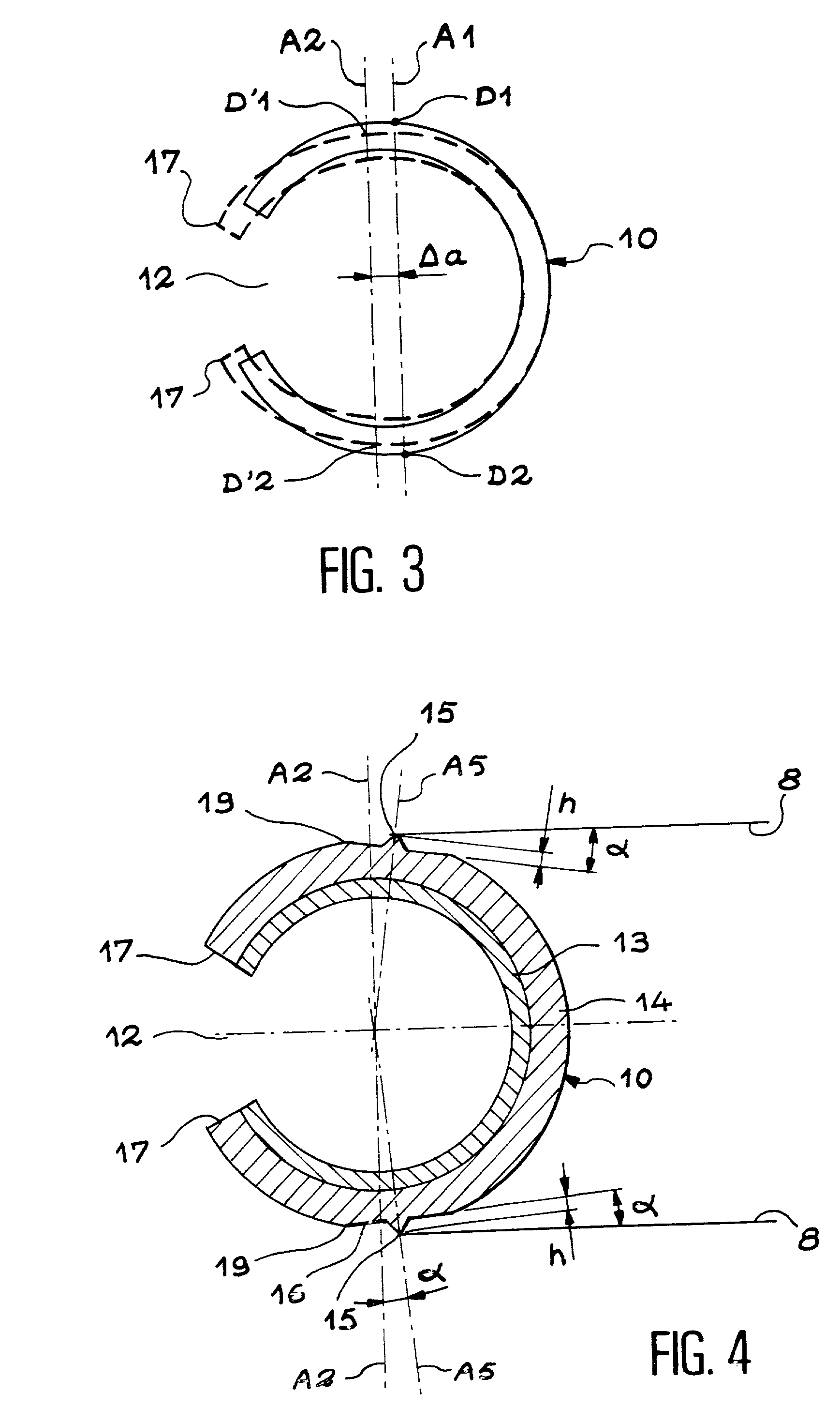
[0022] In reference to FIG. 3, the operation of the gasket according to the invention is based on a principle similar to the gasket of an earlier technique mentioned in the American document, with, however, a preponderant difference which is the following.

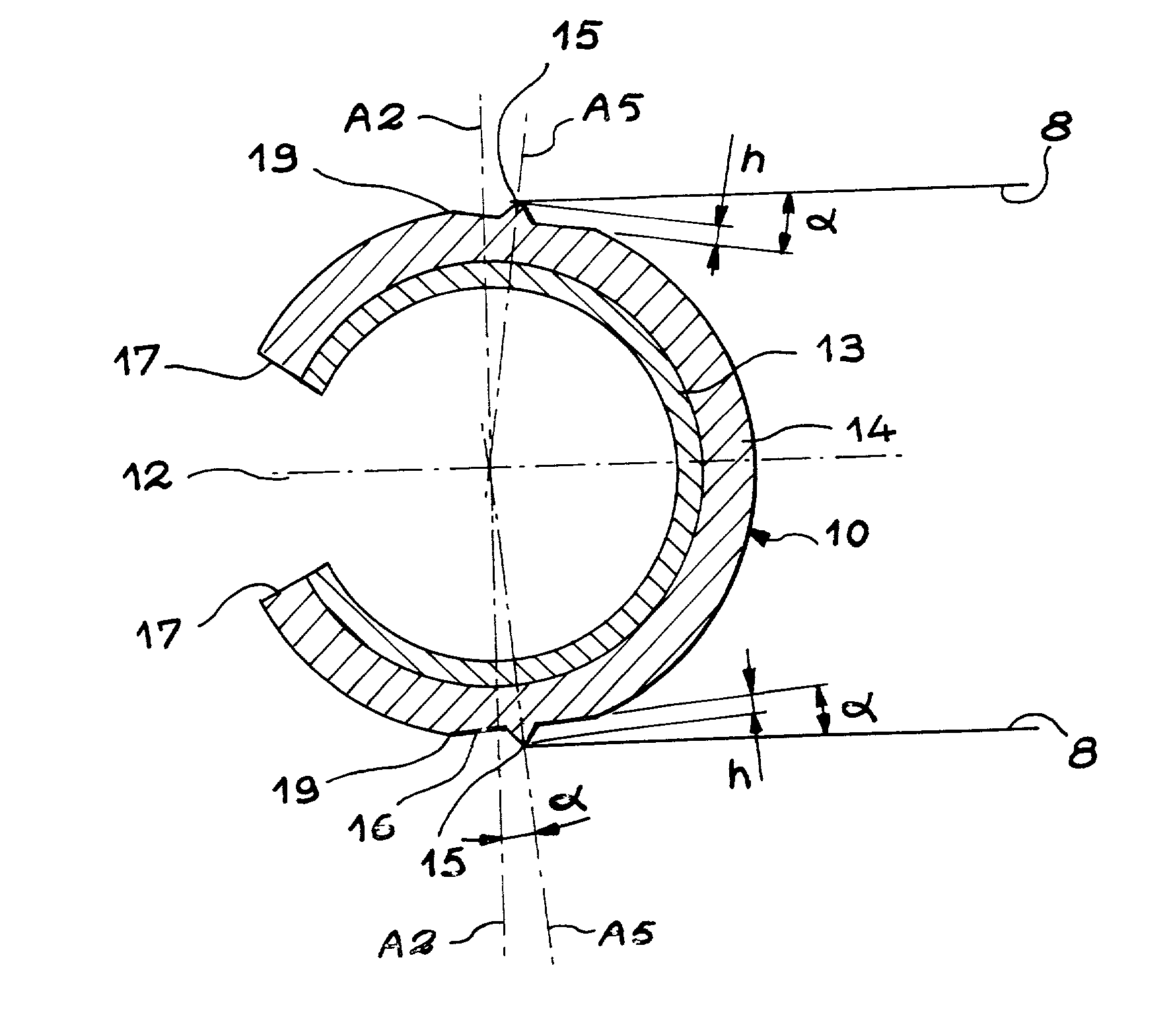
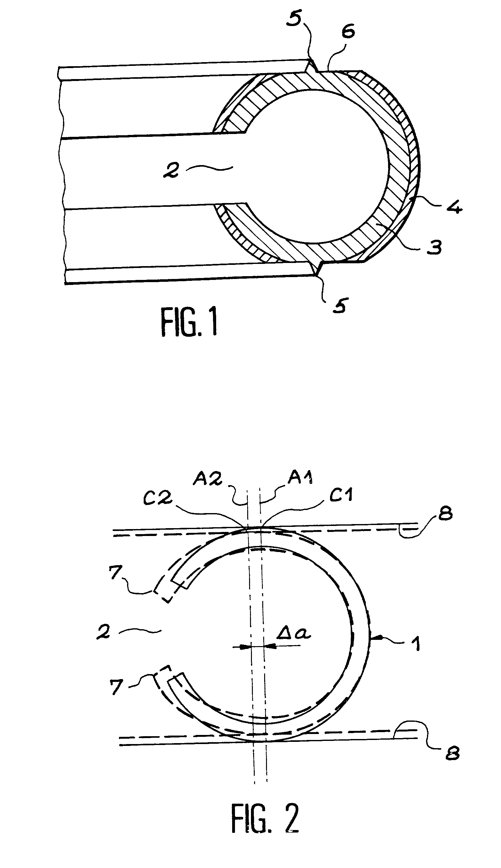
[0023] Gasket 10 has an open cylindrical structure with an opening 12. On the contact surface that will come into contact with the objects to seal, one with respect to the other, it has a projecting part. The latter is placed at a location, identified D1 or D2, that is slightly offset with respect to the center line A2 of gasket 10, which passes through the geometric center of the section of gasket 10. In other words, there is a short distance .DELTA.a between line A1 passing through the two contact points D1 and D2, each forming a projecting part and the center line A2 of gasket 10.

[0024] In this way, in the figure showing the oppositions before and after flattening, we see that gasket 10 shifts slightly to the left, as shown by t...


PUM

PropertyMeasurementUnit
Angleaaaaaaaaaa
Angleaaaaaaaaaa
Heightaaaaaaaaaa

Abstract

The open circular section gasket is not deformed under flattening while nevertheless ensuring the leaktightness of the two spaces to seal. Each contact surface (16) is slightly inclined and has a slightly offset projecting part (15) such that the summits of the two projecting parts define an axis that is offset with respect to the center line (A2) of the general circular shape of the gasket (10). When the gasket is flattened, the contact surfaces (16) tend to become parallel, the projecting parts (15) come closer to the center line (A2). Application to cases of static sealing.

Description

SCOPE OF INVENTION[0001] The invention relates to the domain of static sealing, notably the elastic metal gasket that must provide a seal with a preload less than that necessary to ensure the efficiency of a gasket with a spring core.PREVIOUS TECHNIQUE AND PROBLEM AT HAND[0002] In view of their insensitivity to corrosive fluid, their good behavior at high and low temperatures and their good resistance over time, metal gaskets are used for a variety of applications, among which can be cited, in a non-limiting manner, the chemical, petroleum and nuclear industries, as well as the automotive and aerospace sectors. The quality of the seal provided by a gasket depends notably on the specific pressure developed between the contact surfaces of the gasket and the flanges of the assembly in which the gasket is placed. During the initial tightening of the assembly, the specific pressure must be sufficient to allow the adaptation of the gasket to the surface irregularities of the flanges. It i...

Claims


Application Information

Patent Timeline
IPC IPC(8): F16J15/08F02F11/00
CPCF16J15/0893
Inventor CAPLAIN, PHILIPPEMIRABEL, LAURENTROUAUD, CHRISTIAN
Owner GARLOCK FRANCE
Why Eureka
Try Eureka