
High resolution graphics side channel in video conference

a video conference and side channel technology, applied in the field of video conferencing, can solve the problems of losing the normal conference video source during the display of the alternate video source, and unable to simultaneously display an alternate video sour

Active Publication Date: 2002-10-24
HEWLETT PACKARD DEV CO LP
View PDF17 Cites 27 Cited by
  • Summary
  • Abstract
  • Description
  • Claims
  • Application Information

AI Technical Summary

Benefits of technology

[0011] Using the present invention, each time the alternate video source is changed, the alternative video source will be displayed to the remote site as a live image and will share bandwidth of the normal conference video. Conversely, when the alternate video source is static, the alternative video source will be displayed as a still image. This way, the channel bandwidth of the normal conference video is affected only when necessary. The alternate video source can be displayed either on a separate second monitor or in conjunction with the normal videoconference using picture-in-picture (PIP) on a single monitor. Additionally, the user is not required to manually select when and how to view the alternate video source since this is done automatically.

Problems solved by technology

They cannot, however, simultaneously display an alternate video source that can be displayed along with the normal videoconference source of the system.
Moreover, although some videoconferencing systems have the capability to preview an alternate video source, the user is forced to manually select whether the alternate video source should be transmitted as a live or still frame image.
In all prior art systems, however, the normal conference video source is lost during the display of the alternate video source.
Second, even if a live previewed image can be automatically transmitted, it is not transmitted in a high-resolution image format.

Method used


Image

  • High resolution graphics side channel in video conference
  • High resolution graphics side channel in video conference
  • High resolution graphics side channel in video conference

Examples


Embodiment Construction

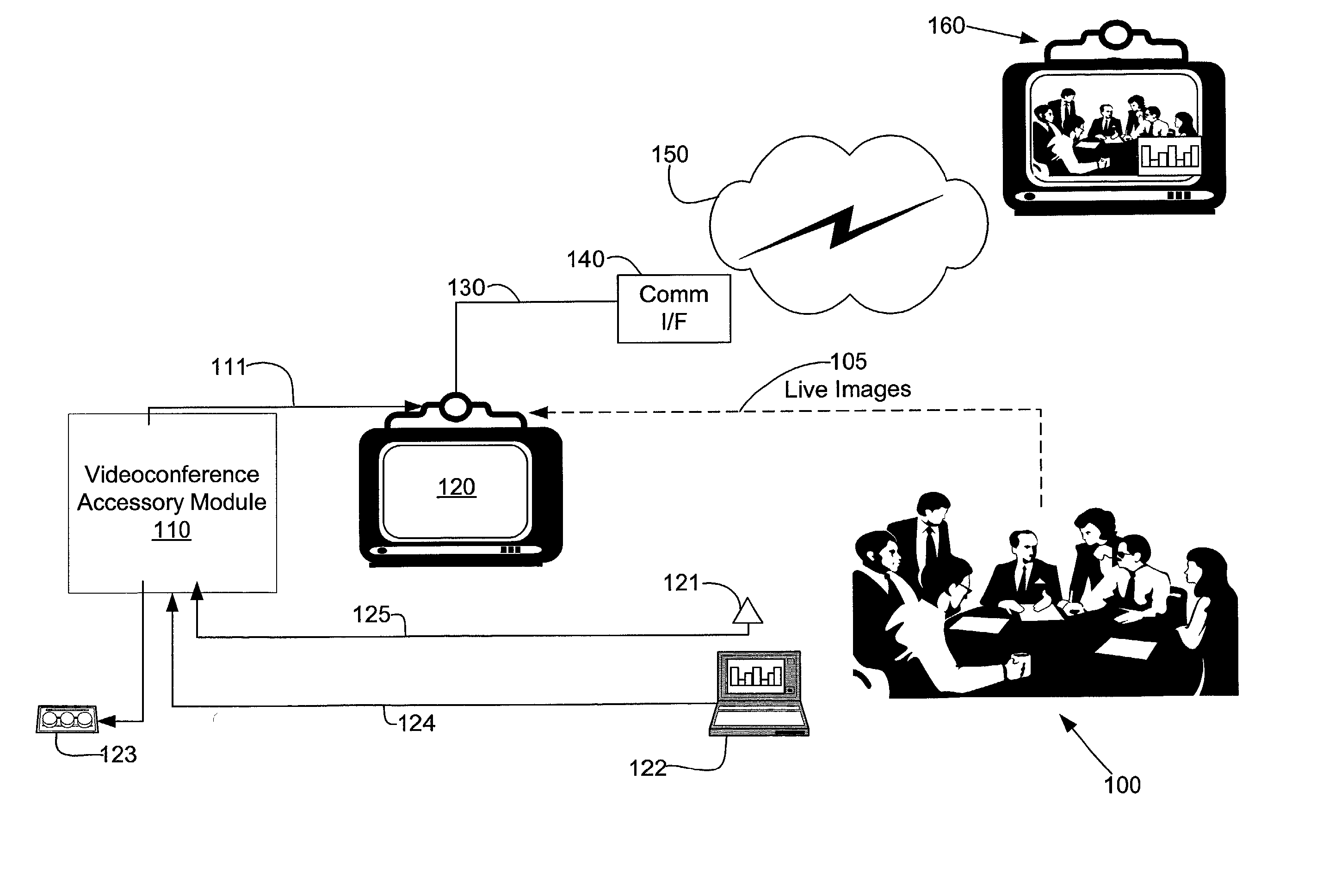
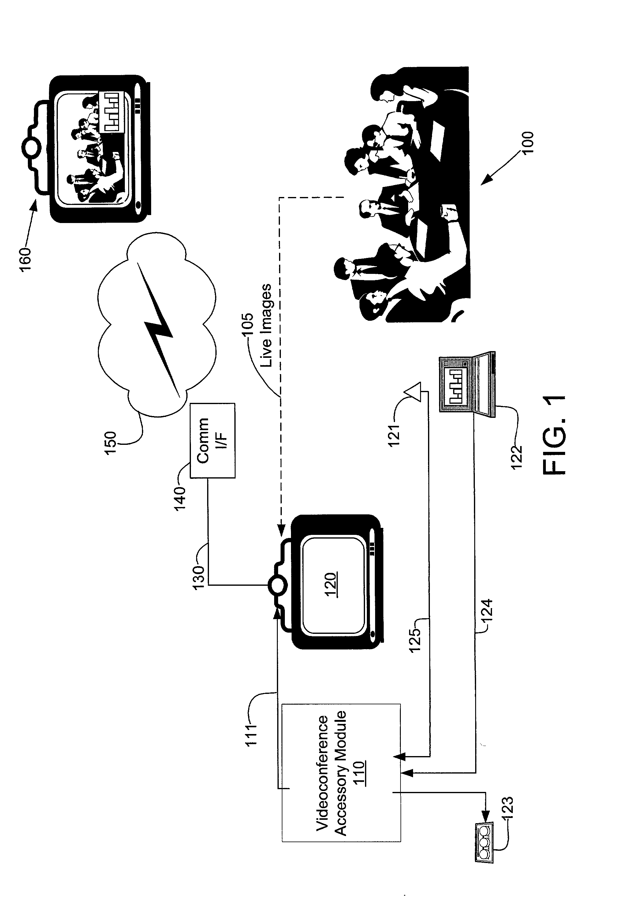
[0019] FIG. 1 shows a videoconference unit 120 located at a local site 100. The videoconference unit 120 captures live video images 105 and audio of users at a local site 100. The videoconference unit 120 then transmits the live video images 105 and the audio to a communications interface 140 through a carrier channel 130. The communications interface 140 transmits the signals to a remote site 160 by way of a communications path 150. Examples of the communications path 150 include, for example, ISDN, Internet, etc. The users of the videoconference unit 120 at the local site 100 can thus communicate both visually and audibly with users of a similar videoconference system at the remote site 160. The users at the remote site 160 will see and hear the video and sound generated by the users of the videoconference unit 120 at local site 100. Because the videoconference unit 120 operates bi-directionally, users of a similar videoconference unit at the remote site 160 can likewise transmit ...


PUM


Abstract

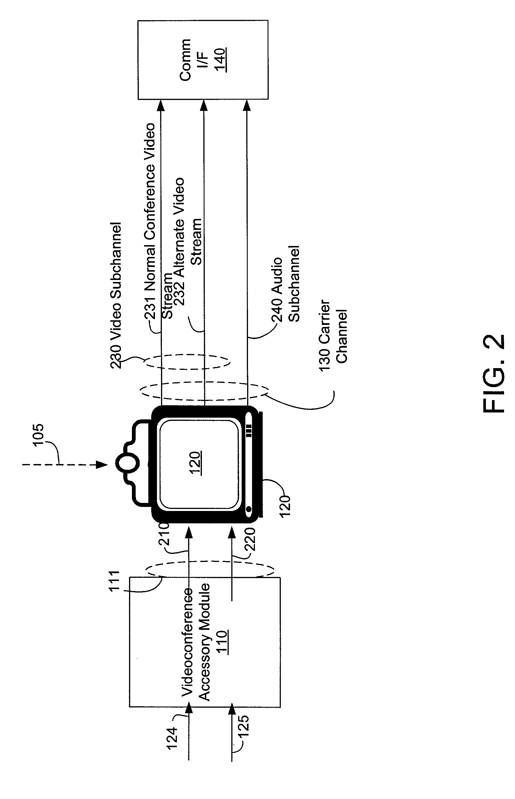
A videoconference system can automatically transmit first and second images from a local site to a remote site where the first image is a high-resolution live image and the second image may be transmitted either as a high-resolution live or still frame image. Two video streams representing the first and second images are transmitted together to the remote site within a single carrier channel. The second image is transmitted as a still image whenever the second image is static to conserve bandwidth.

Description

[0001] This application claims the benefit of U.S. Provisional Application Serial No. 60 / 278,305 filed on Mar. 22, 2001.[0002] 1. Field of the Invention[0003] The present invention relates generally to video conferencing, and more particularly to transmission of alternate image sources through a graphics side channel.[0004] 2. Description of Related Art[0005] Videoconferencing systems provide a means for users at a local site to conference with users at a remote site by way of audio and video transmissions. These systems typically consist of a video source and an audio source that transmit images and sound from the local site for viewing and listening by the users at the remote site.[0006] Due to bandwidth limitations, current videoconferencing systems can display either a conference camera image, typically showing the conference participants (i.e., the normal videoconference source), or a document camera image (e.g., an alternate video source), typically showing a computer screen d...

Claims


Application Information

Patent Timeline
IPC IPC(8): H04N7/12H04N7/14H04N21/2365H04N21/434
CPCH04N7/12H04N21/4347H04N21/2365H04N7/147
Inventor KENOYER, MICHAELVANDERWILT, PATRICK
Owner HEWLETT PACKARD DEV CO LP
Learn More