Balance beam

US20020177508A1Inactive Publication Date: 2002-11-28SPRING FORWARD
0 Cites 13 Cited by

Patent Information

Authority / Receiving Office
US · United States
Current Assignee / Owner
Publication Date
2002-11-28
Estimated Expiration
Not applicable · inactive patent

Smart Images

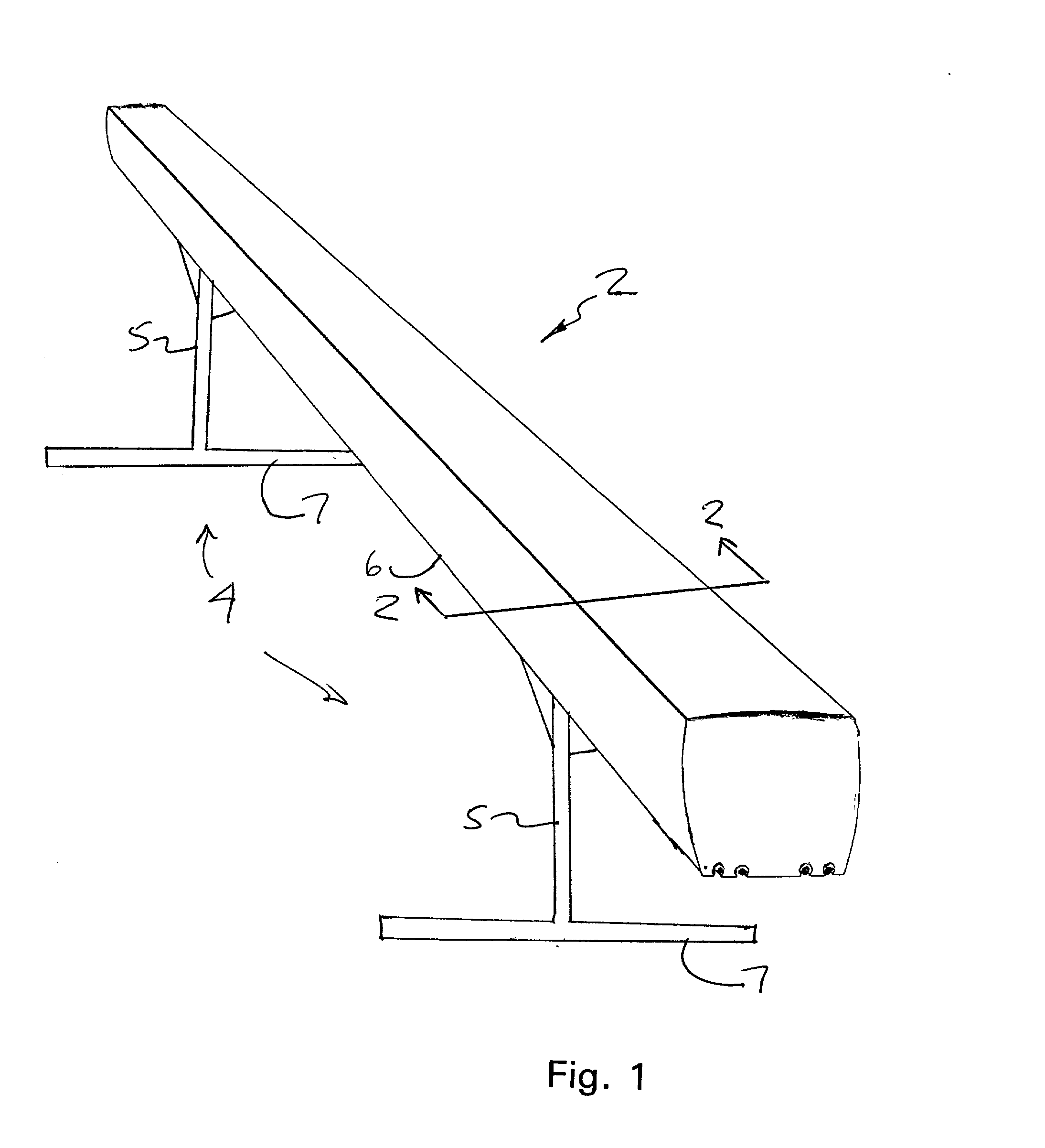
  • Figure 1
    Figure 1
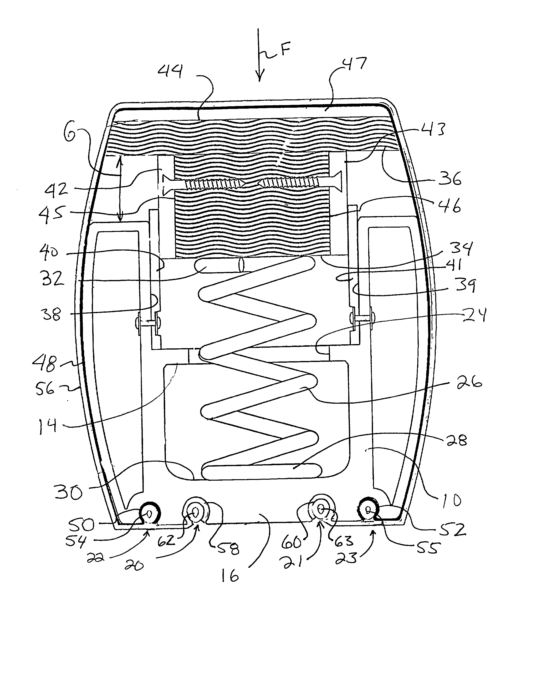
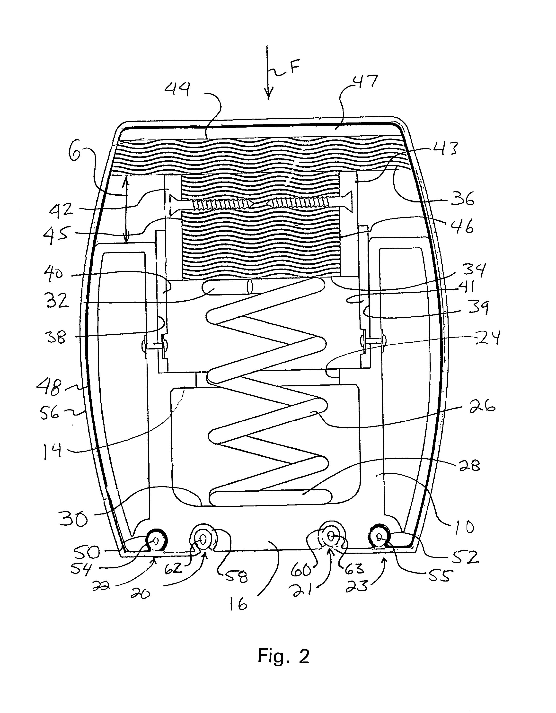
  • Figure 2
    Figure 2
  • Figure 3
    Figure 3
Patent Text Reader

Abstract

A balance beam having a shock absorbing capability. The balance beam comprises an elongate beam member, an elongate beam support core supporting the elongate beam member, and a resilient element located between the beam member and the beam support core. The resilient element allows the beam member to move relative to the beam support core when a vertically downward force is exerted on the beam member to absorb shock imparted to the balance beam by a user.
Need to check novelty before this filing date? Find Prior Art

Description

FIELD OF THE INVENTION

[0001] The present invention relates to an improved balance beam for use by gymnasts.BACKGROUND OF THE INVENTION

[0002] While a variety of different balance beams are currently available in the marketplace, they suffer from the drawback of not providing sufficient shock absorbing capabilities when a gymnast jumps or otherwise performs a feat on the balance beam, which requires the gymnast to momentarily leave the balance beam, and then return to the balance beam. As a result of the failure to provide a sufficient shock absorbing capability, gymnasts are occasionally injured during the performance of the feat.SUMMARY OF THE INVENTION

[0003] Wherefore, it is an object of the present invention to overcome the above noted drawbacks of the prior art balance beams.

[0004] Another object of the present invention is to provide a balance beam which provides a sufficient shock absorbing capability when a gymnast performs a feat on the balance beam to lessen the impact when ...

Examples

Embodiment Construction

[0019] Referring now to FIG. 1, the basic components of the improved balance beam according to the present invention will now be discussed. As can be seen in this Figure, the present invention generally comprises an elongate balance beam 2 which is supported by a pair of conventional balance beam supports 4. Each one of the balance beam supports 4 generally comprises a vertically extending support member 5 having a top end secured to a bottom surface 6 of the balance beam 2 and a horizontally extending support member 7 which is secured to a bottom end of the vertically extending support member 5 and engages a floor or some other support surface. As can be seen in this Figure, each one of the balance beam supports 4 also has at least one lateral support (not numbered) interconnecting an intermediate portion of the vertically extending support member 5 with a bottom surface 6 of the balance beam 2 to provide lateral stability for the balance beam support 4. As the lateral, horizontal ...