Valve assembly with Anti-tip features

Active Publication Date: 2022-06-23
DELPHI TECH IP LTD
View PDF0 Cites 0 Cited by
  • Summary
  • Abstract
  • Description
  • Claims
  • Application Information

AI Technical Summary

Benefits of technology

[0004]Briefly described, a valve assembly is configured to be received within a receiving bore which extends along a receiving bore axis from an outer surface to a receiving bore inner end, the receiving bore being stepped in diameter such that a first diameter which is proximal to the receiving bore inner end is smaller in diameter than a second diameter which is axially between the first diameter and the outer surface and such that a third diameter which is axially between the second diameter and the outer surface is larger in diameter than the second diameter. The valve assembly includes a valve housing which is configured to be received within the receiving bore and which extends along a valve housing axis from a valve housing inner end, which is proximal to the receiving bore inner end when the valve housing is in the receiving bore, to a valve housing outer end which is distal from the receiving bore inner end when the valve housing is in the receiving bore, the valve housing having a first port, a second port, and a third port. The valve assembly also includes a valve member within the valve housing which is moveable therein, thereby providing different levels of fluid communication between the first port and the second port. The valve housing includes a first annular groove on an outer periphery of the valve housing such that the first annular groove is centered about the valve housing axis and such that a first sealing ring is provided in the first annular groove and configured to engage the first diameter, thereby sealing the first port from the second port at the outer periphery, the first annular groove being bounded axially by a first lower annular groove flange and a fir

Problems solved by technology

Since one or more of the passages intersect the peripheral wall of the receiving bore, it is a concern that the sealing rings may be damaged as they pass across the passages during installation or removal of the control valve since the passages create sharp edges where they intersect with the receiving bore.
However, it may be dif

Method used


Image

  • Valve assembly with Anti-tip features
  • Valve assembly with Anti-tip features
  • Valve assembly with Anti-tip features

Examples


Embodiment Construction

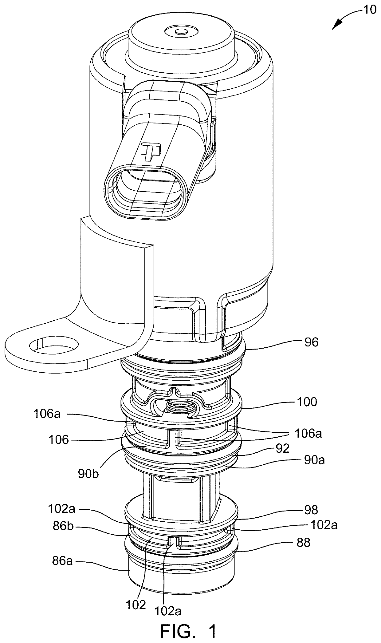
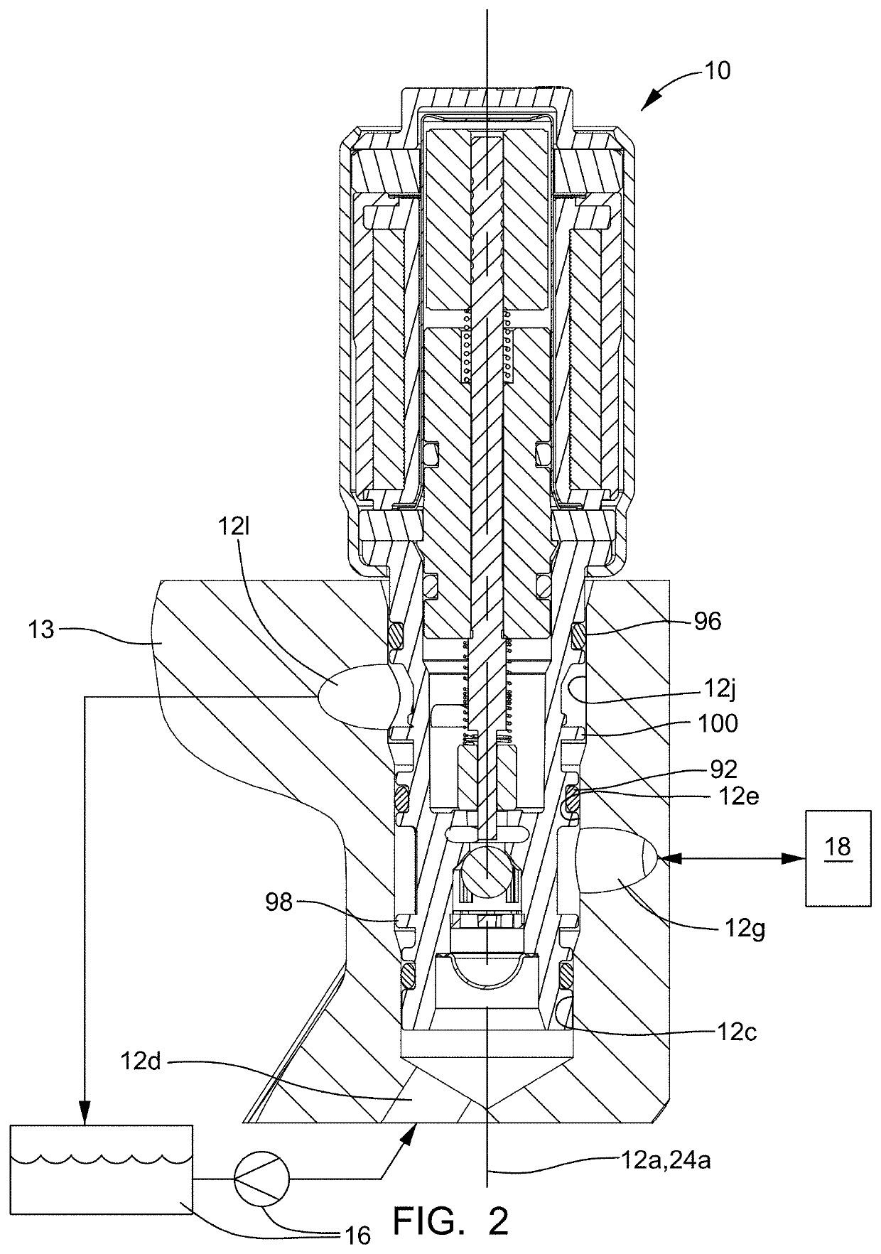
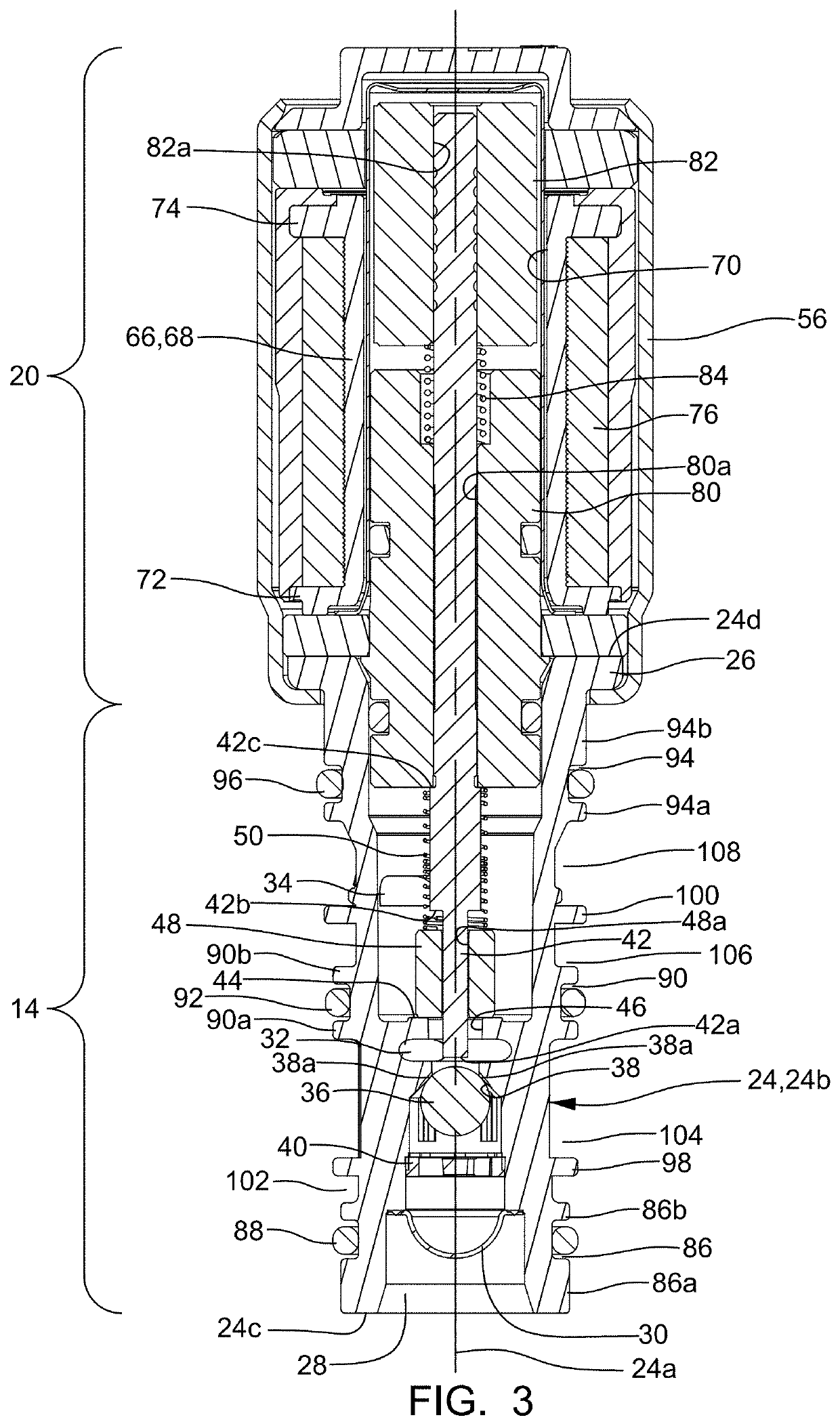
[0011]In accordance with a preferred embodiment of this disclosure and referring initially to FIGS. 1-4, a solenoid-actuated control valve 10 is shown, hereinafter referred to as valve assembly 10. Valve assembly 10 is configured to be received within a receiving bore 12, by way of non-limiting example only, of a cylinder head 13 of an internal combustion engine, such that receiving bore 12 is centered about, and extends along, a receiving bore axis 12a. Valve assembly 10 includes a hydraulic subassembly 14 in fluid communication with a fluid source 16 and a working device 18. As illustrated herein, fluid source 16 may be, by way of non-limiting example only, a reservoir and pump. Working device 18 may be, by way of non-limiting example only, a multi-step valve train device for an internal combustion engine of a motor vehicle. Valve assembly 10 also includes solenoid subassembly 20 which is connected to hydraulic subassembly 14 and which controls fluid communication from fluid sourc...


PUM


Abstract

A valve assembly includes a valve housing having a first port, a second port, and a third port. A valve member within the valve housing is moveable therein to alter fluid communication between the first and second ports. The valve housing includes a first annular groove such that a first sealing ring is provided in the first annular groove, thereby sealing the first port from the second port when installed in a receiving bore. The valve housing also includes a second annular groove such that a second sealing ring is provided in the second annular groove, thereby sealing the second port from the third port in the receiving bore. The valve housing also includes a first anti-tip flange extending radially outward to a greater extent than the first annular groove and a second anti-tip flange extending radially outward to a greater extent than the second annular groove.

Description

TECHNICAL FIELD OF INVENTION[0001]The present invention relates to a valve assembly; more particularly to a valve assembly which includes features which preventing tipping of the valve assembly during installation and removal from a receiving bore.BACKGROUND OF INVENTION[0002]Control valves are widely used to control fluid flow and pressure between multiple ports. In one particular arrangement, a receiving bore extends into a body and the control valve is inserted into the receiving bore. Two or more passages extend through the body and intersect with the receiving bore such that the control valve is designed to control fluid flow and pressure between the passages. The passages may include a supply passage, a control passage, and a vent or exhaust passage where one or more of these passages intersect with the peripheral wall of the receiving bore and the passages are spaced apart axially within the receiving bore. In order to prevent communication between the passages, the control v...

Claims


Application Information

Patent Timeline
IPC IPC(8): F16K11/07F16K27/04
CPCF16K11/0708F16K27/041F16K2200/501F16K27/029F16K31/0634
Inventor DINKEL, MICHAEL J.PLASCENCIA, SALVADOR
Owner DELPHI TECH IP LTD
Why Eureka
Try Eureka