System and method for measuring bending in a pin member

a pin member and measurement system technology, applied in the direction of force/torque/work measurement apparatus, instruments, screws, etc., can solve the problems of eluded effective difficult measurement of bending forces or moments, and unobvious bending directions with respect to ideals, etc., to achieve highly accurate bending moment information, measure the magnitude and direction of bending moments, and achieve the effect of reliable and accurate measuremen

Inactive Publication Date: 2003-01-02
NORTHROP GRUMMAN SYST CORP
View PDF2 Cites 26 Cited by
  • Summary
  • Abstract
  • Description
  • Claims
  • Application Information

AI Technical Summary

Benefits of technology

0025] With the presently preferred embodiments of the invention, it is possible to reliably and accurately measure the magnitude and direction of bending moments in a pin member, in real or near real time, and under actual operating conditions. Using, among other things, an arrangement in which net axial strain, i.e., net tension and compression measurements, are canceled out, and optionally in which the measurement device switches between tension / compression measurements and bending measurements, it is possible to obtain highly accurate bending moment information, including not only the presence of bending forces and their magnitude, but also direction as a function of time. With the embodiments disclosed herein, it is possible to automatically switch in periodic fashion from measuring axial strain or preload while disregarding or isolating out bending and torsional stress, and independently or alternately measure bending magnitude and direction while disregarding or isolating out axial and torsional stresses. This permits the essentially simultaneous measurement of bending moments and axial loads.

Problems solved by technology

The effective measurement of bending forces, however, has eluded effective measurement.
The direction of bending can be important in some applications, for example, because pin member through-hole radial translation with respect to the pin member shaft often can result in unobvious bending directions with respect to the ideal.
The measurement of bending forces or moments often is particularly difficult, however, because the direction of the force can change, sometimes rapidly, over time.

Method used


Image

  • System and method for measuring bending in a pin member
  • System and method for measuring bending in a pin member
  • System and method for measuring bending in a pin member

Examples


Embodiment Construction

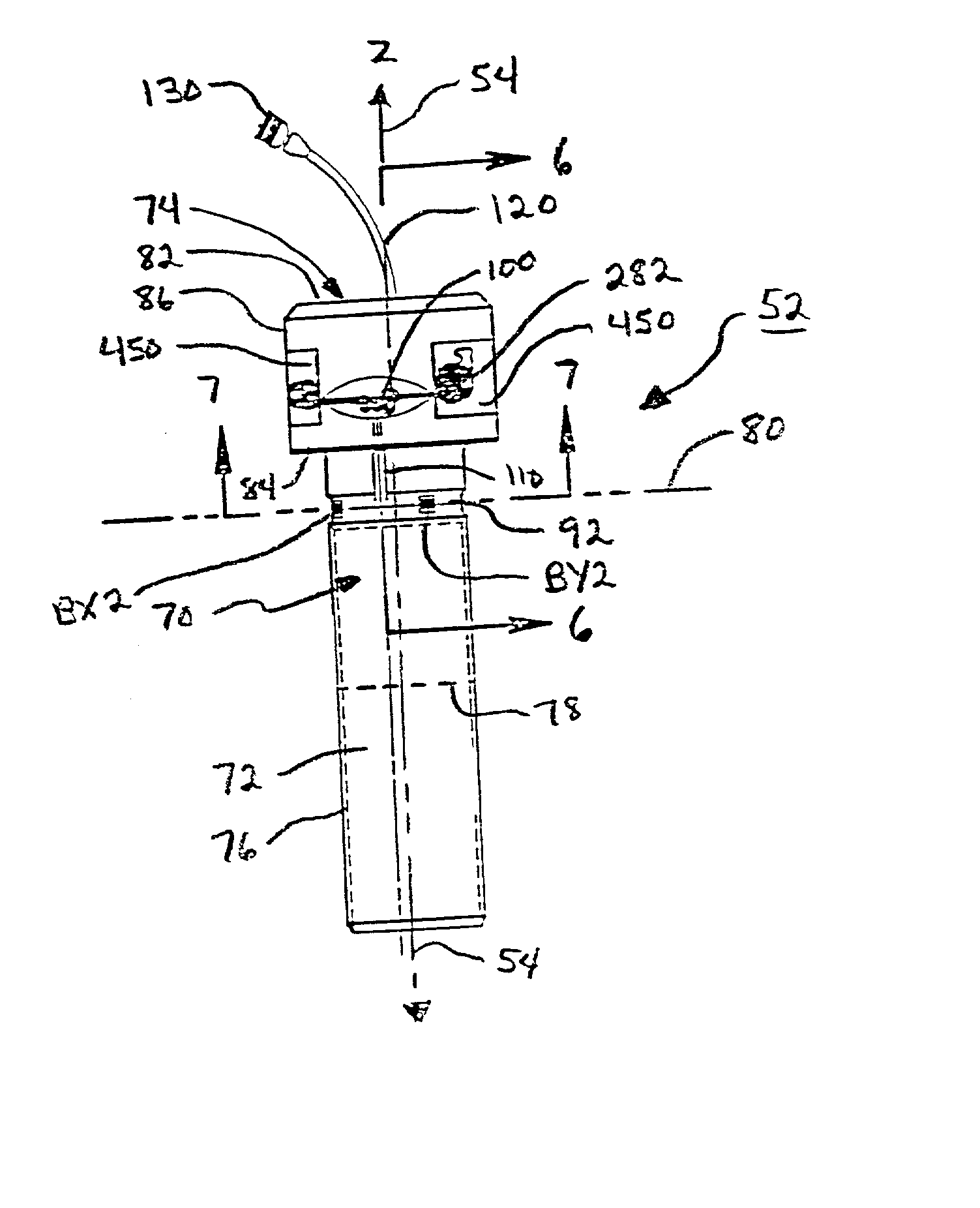
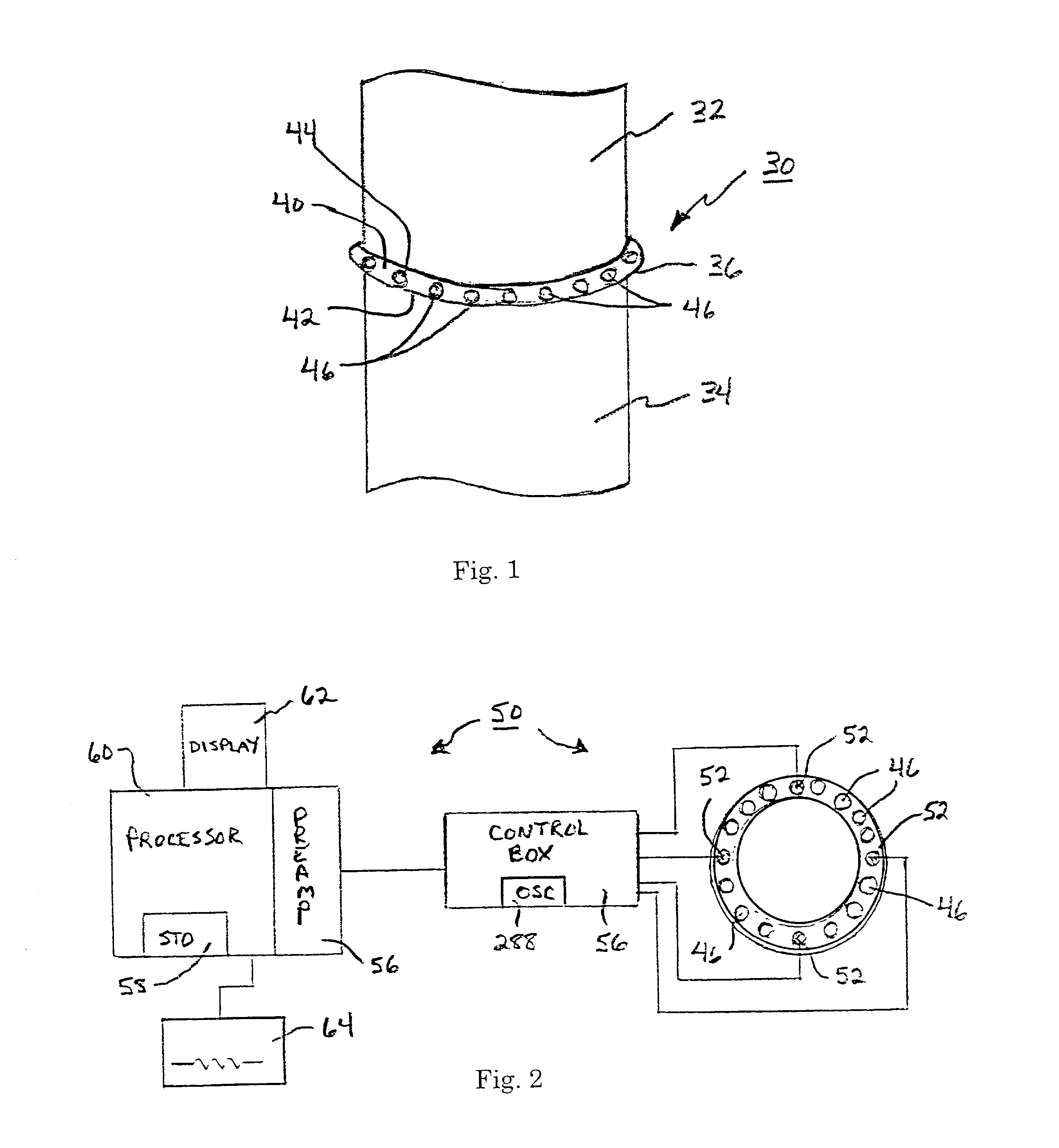
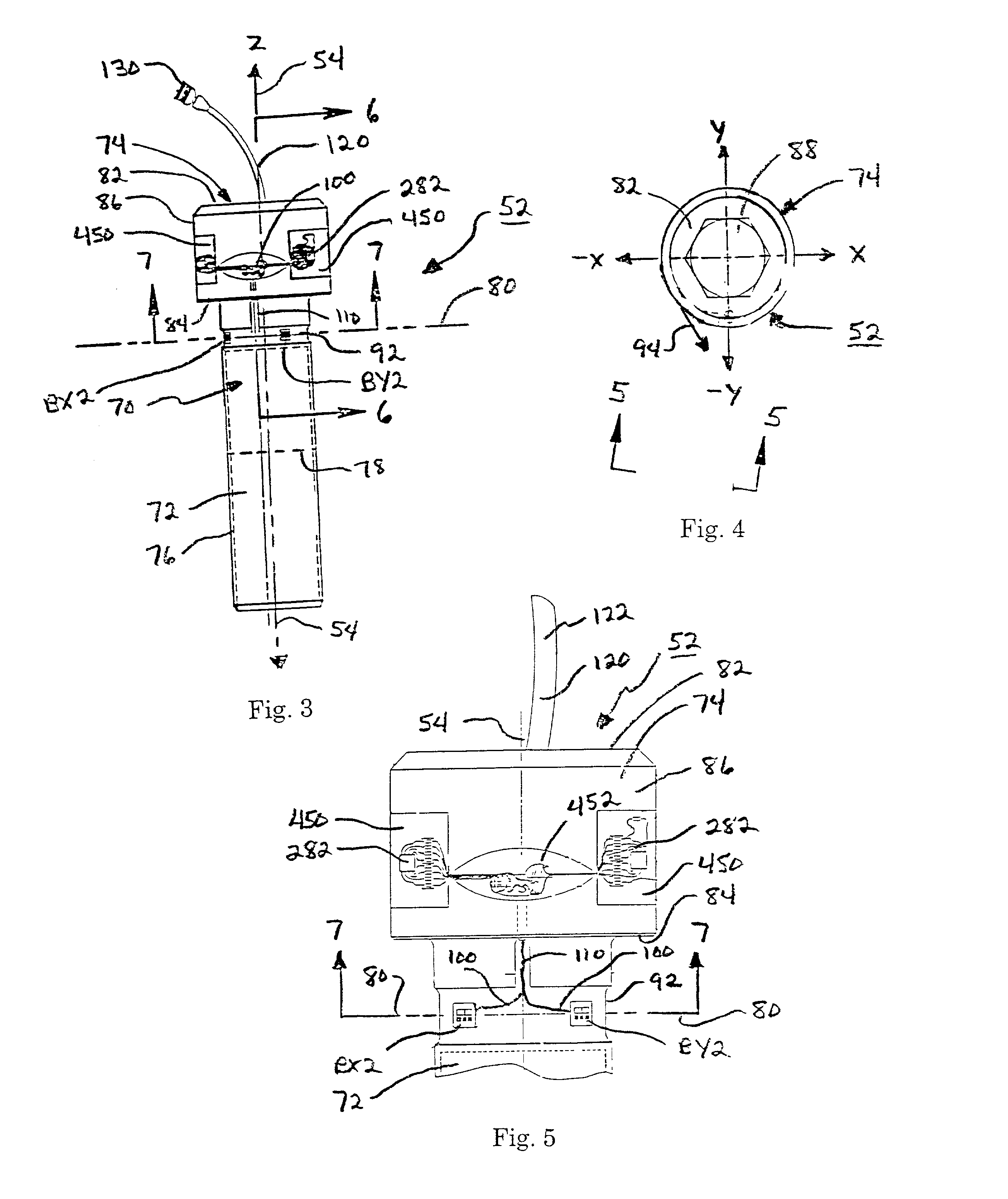
[0042] Reference will now be made in detail to the presently preferred embodiments and methods of the invention as illustrated in the accompanying drawings, in which like reference characters designate like or corresponding parts throughout the drawings. It should be noted, however, that the invention in its broader aspects is not limited to the specific details, representative devices and methods, and illustrative examples shown and described in this section in connection with the preferred embodiments and methods. The invention according to its various aspects is particularly pointed out and distinctly claimed in the attached claims read in view of this specification, and appropriate equivalents.

[0043] In accordance with one aspect of the invention, an instrumented pin member is provided. The instrumented pin member according to this aspect may take the form of or comprise a bolt, a screw, a pin, or the like. In many applications the pin member will have a round or substantially r...


PUM

PropertyMeasurementUnit
lengthaaaaaaaaaa
diameteraaaaaaaaaa
radial diameteraaaaaaaaaa

Abstract

An instrumented pin member is provided that is capable of measuring bending moments, and optionally of measuring bending and axial strain in real or near real time. The instrumented pin member includes a pin member body disposed about a pin member axis, wherein the pin member body includes a bending portion. A sensing device is positioned at the pin member body within the bending portion for sensing a bending strain in the bending portion exclusive of a net axial strain, and for outputting a sensor measurement signal representative of the bending strain. A sensor measurement signal output device is provided for outputting the sensor measurement signal from the sensor device. A related system includes a plurality of pin members, among other things. Related methods also are disclosed.

Description

[0001] 1. Field of the Invention[0002] The present invention relates to instrumented coupling devices and methods and, more specifically, to apparatus and methods for measuring or predicting bending in a pin member used to couple a joint.[0003] 2. Description of the Related Art[0004] A common means of joining two mechanical bodies together involves the use of one or more pin members disposed through aligned and mating apertures. A "pin member" as the term is used herein may be interpreted broadly to include such devices as bolts, screws, pins, axles, and the like. The joint may take any one of a number of forms. It may, for example, comprise a flanged joint between two pipes, pressure vessel housings, a flanged joint between two solid rocket motor casings, clevis and yoke assemblies, etc.[0005] Under operating conditions, a variety of forces act on the pin member. These forces include tension and compression forces along the longitudinal axis of the pin member, or with force compone...

Claims


Application Information

Patent Timeline
Patent Type & Authority Applications(United States)
IPC IPC(8): F16B31/02G01L1/00G01L1/22G01L5/00
CPCG01L1/2225
Inventor SMITH, DOUGLAS E.TOTMAN, PETER D.EVERTON, RANDY L.JEAN, PAUL A.BUNDERSON, MARVIN D.EGGETT, MARK R.BORGSTROM, RANDY L.
Owner NORTHROP GRUMMAN SYST CORP
Why Eureka
Try Eureka