Drywall finishing system

a finishing system and drywall technology, applied in the field of drywall construction, can solve the problems of requiring an extended drying time, thick layer will tend to experience shrinkage and cracking, and thick wedges of mud f are built up on both sides of the corner member at significant labor and material costs

Inactive Publication Date: 2003-02-06
SMYTHE TIMOTHY D JR
View PDF0 Cites 30 Cited by
  • Summary
  • Abstract
  • Description
  • Claims
  • Application Information

AI Technical Summary

Problems solved by technology

Because the layer is thick it requires an extended drying time, typically over night.
Moreover, the thick layer will tend to experience shrinkage and cracking while drying.
As with the sharp corner bead, thick wedges of mud F are built up on both sides of the cor

Method used


Image

  • Drywall finishing system
  • Drywall finishing system
  • Drywall finishing system

Examples


first embodiment

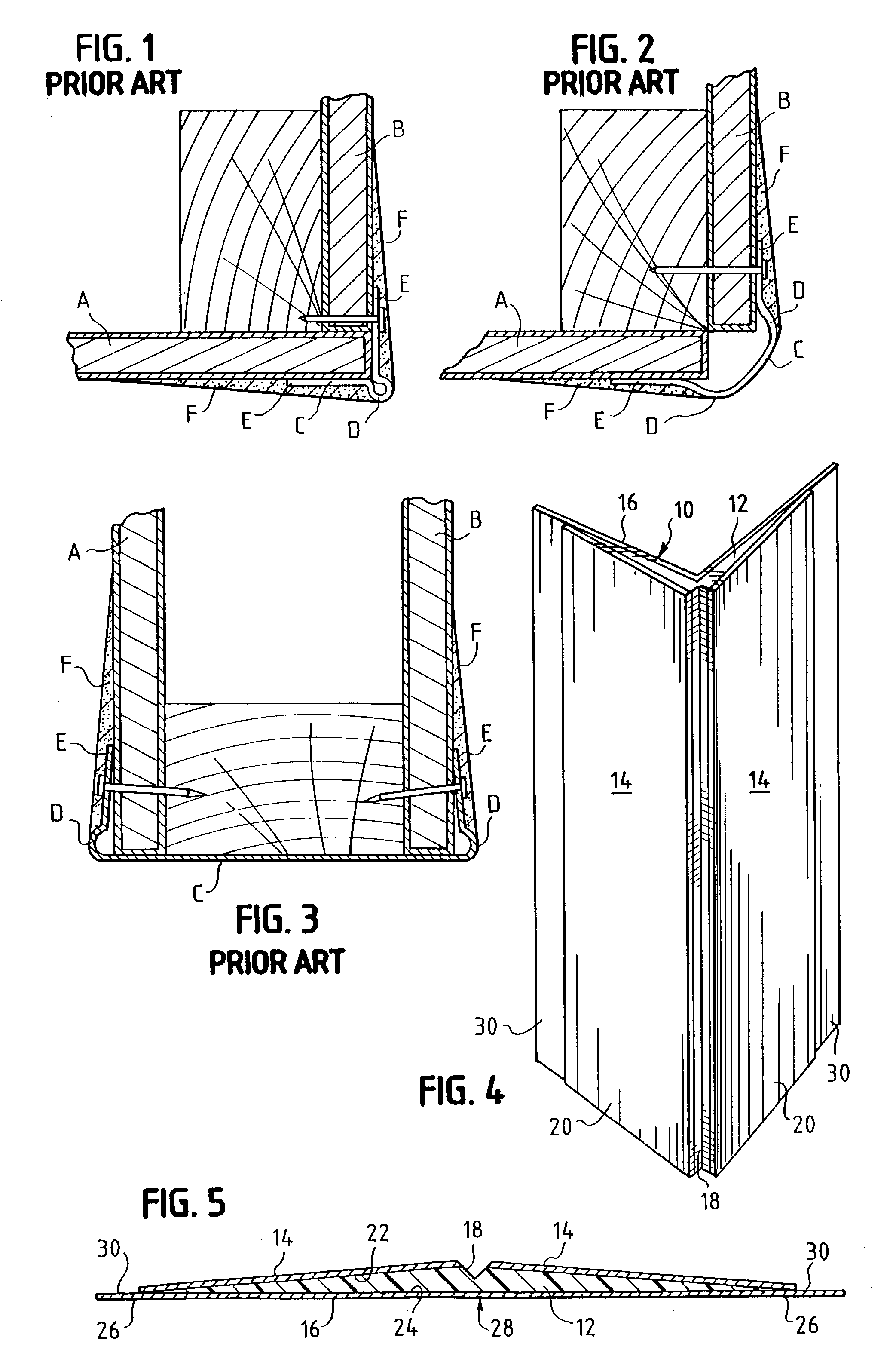
[0052] Referring to FIGS. 4 and 5, the present invention, that will be called "Ultra-Flex", is seen generally at 10. This embodiment can be used for inside or outside corners. Its construction is that of an elongated semi-rigid member 12 with an interior layer of covering material 14 and an exterior layer of finishing material 16 laminated thereto. The semi-rigid member 12 can be plastic, metal, or other flexible, but strong material, with high impact plastic such as that used to construct modern cola bottles being preferred. The member can be supplied in 10 or 12 foot lengths, or any other convenient length, or it can be supplied on a roll of 100 feet or any other convenient length. Running the length of the member is a groove 18. The groove divides the piece into two flanges 20 that can be repeatedly bent to form any angle from about 15 degrees to about 345 degrees. In this manner, the piece can be bent to match any inside or outside corner. The elongated semi-rigid member has a f...

second embodiment

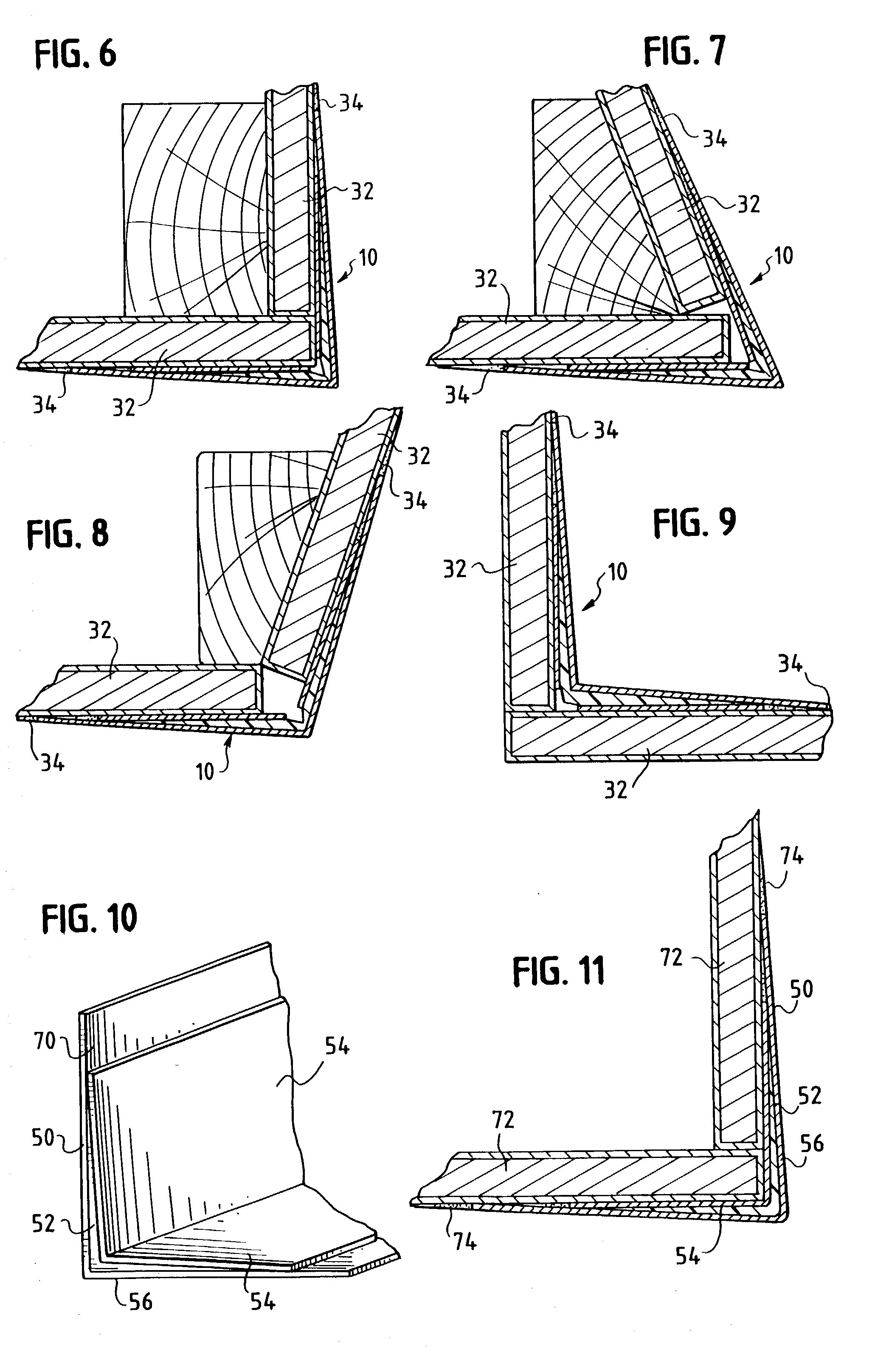
[0067] FIG. 11 shows the trim piece of the second embodiment installed on a drywall outside corner. Drywall sheets 72 form a conventional right angle, outside corner. The trim piece 50 is continuously adhered to the drywall with mud as described above. The edges between the trim piece 50 and drywall 72 are feathered with a relatively small quantity of mud 74 to provide a smooth surface. The exterior surface of the trim piece is not coated with mud, however, as was customary with prior art corner beads. Compare FIG. 11 to FIG. 1. There is a dramatic reduction in the amount of drywall mud utilized--up to 75% less mud. The reduction in the quantity of mud directly translates to corresponding dramatic reductions in the amount of drying time and labor.

third embodiment

[0068] FIGS. 12 and 13 illustrate the trim piece 110 of the invention comprising a rounded or bullnose right angle outside corner piece. Trim piece 110, as with the first two embodiments, comprises a semi-rigid member 112 with an interior layer of covering material 114 and an exterior layer of finishing material 116 laminated thereto. The semi-rigid member 112 can be preformed with a permanent 88-90.degree. radius 118. The exact angle is not critical and can be preformed to other angles encountered in the field such as 135 degrees, or any other angle. The preferred material is high impact plastic, with a uniform thickness of 0.057 inches in the radius. The radius is a true circular arc--there are no ridges or beads. The semi-rigid member 112 further comprises flanges 120 that can taper laterally from a maximum thickness at radius 118 to a minimum thickness near lateral edges 126, or can taper laterally from maximum thickness at a point slightly away from the radius 118 to a minimum ...


PUM


Abstract

A drywall finishing system for finishing normal inside and outside corners of any angle. The finishing system comprises a preformed trim piece comprising a semi-rigid member that is relatively thick in the center and tapers laterally to a thin edge or is stepped forming a thick and thin portion. A layer of fibrous can be bonded to the inside surface of the semi-rigid member for receiving joint compound to continuously bond the trim piece to the dry wall. A layer of finishing material can be bonded to the exterior surface of the semi-rigid member. The finishing system can be attached to a wall with fasteners such as nails.

Description

CROSS REFERENCE[0001] This application is a Continuation-In-Part of co-pending application Ser. No. 09 / 780,756 filed Feb. 10, 2001 which was a Continuation-In-Part of co-pending application Ser. No. 09 / 715,614 filed on Nov. 17, 2000 which was a Continuation of application Ser. No. 09 / 191,861 filed Nov. 12, 1998, now U.S. Pat. No. 6,148,573, which was a Continuation-In-Part of both application Ser. No. 08 / 832,470 filed Apr. 2, 1997, now abandoned and application Ser. No. 08 / 718,137 filled Sep. 18, 1996, now abandoned. These applications (Ser. Nos. 08 / 832,470 and 08 / 718,137) were Continuations-In-Part of parent application Ser. No. 08 / 544,339 filed Oct. 17, 1995, now abandoned.[0002] 1. Field of the Invention[0003] This invention relates generally to the field drywall construction and more particularly to a system of exterior and interior drywall seams and corners that greatly reduces the amount of time, labor and material required to finish a modern structure.[0004] 2. Description of...

Claims


Application Information

Patent Timeline
IPC IPC(8): B32B29/00E04F13/06E04F19/02
CPCB32B29/00E04F13/06E04F19/022E04F2013/063E04F13/068E04F2019/0427
Inventor SMYTHE, TIMOTHY D. JR.
Owner SMYTHE TIMOTHY D JR
Why Eureka
Try Eureka