
Optimally elastic golf club head

a golf club head and elastic technology, applied in the field of optimal elastic golf club head, can solve the problems of poor performance, inability to exhibit the desired stiffness, and too stiff structure,

Inactive Publication Date: 2003-02-06
ORIGIN INC +1
View PDF30 Cites 71 Cited by
  • Summary
  • Abstract
  • Description
  • Claims
  • Application Information

AI Technical Summary

Problems solved by technology

If the dimensions of the drawings are approximately to scale, experience of the present inventors indicates that the structure would be too stiff and would not be able to exhibit the desired stiffness.
Hits near the face perimeter would engage the front edge of the shell and have poor performance.
U.S. Pat. No. 6,348,015 provides mathematical analysis for design of a flexible face, but does not provide adequate flexibility for off-center hits, particularly those near the perimeter of the face.
Hits near the perimeter of the face would involve the front edge of the shell and such hits would not have the desired benefit of spring effect.
Off-center hits do not have the full benefit and near the edge, almost no benefit because the spring effect is absent.
It is too soft and has too much internal vibration-damping behavior to be significant as a spring-effect element.
This bulging slightly reduces the stiffness of such rear structures.
When the face structure is sufficiently thin for the desired elastic properties, structural failure of the face caused by strong hits is a serious problem, especially for woods having uniform face thickness.
Most commercially available driver heads having spring effect reduce this problem by making the face thicker near the central area for greater strength there, but such failure is still common.
This may cause many yards loss of distance.
All prior art designs suffer from the defects described above, most having defects 1 through 5 and none provide means for reducing or eliminating all 5 defects.

Method used


Image

  • Optimally elastic golf club head
  • Optimally elastic golf club head
  • Optimally elastic golf club head

Examples


Embodiment Construction

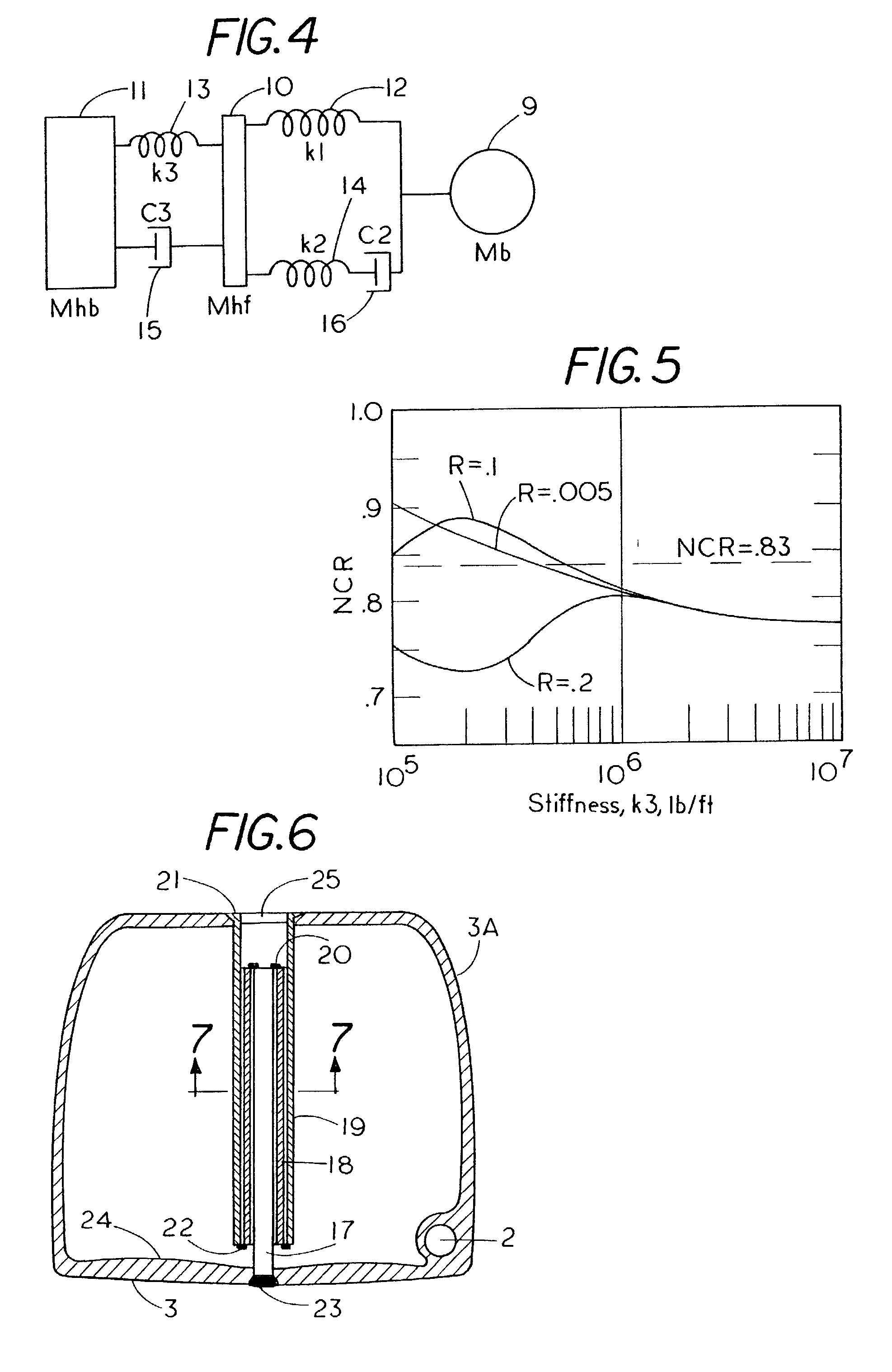
[0080] When stiffness, mass, and internal damping characteristics of the face have suitable values, the result is commonly called the "spring effect" or the "trampoline effect", and this can add 5 to 20 yards to a golfer's hit.

[0081] Off-center hits have basic differences from center hits. They must be studied by much more complicated analysis and / or evaluated experimentally. Off-center hits ordinarily give much less distance and altered launch direction of the ball for drives as compared to center hits. The design problem is generally to minimize this change of launch direction and this loss of distance. The stiffness, moment of inertia of the head, its face curvature, the amount of the off-center distance, the shear coefficient of restitution (or an equivalent), and other factors must be considered in addition to the concept of NCR.

[0082] The present inventors used computer-based analysis to study the face stiffness problem with a model of club head-ball impact which is illustrate...


PUM


Abstract

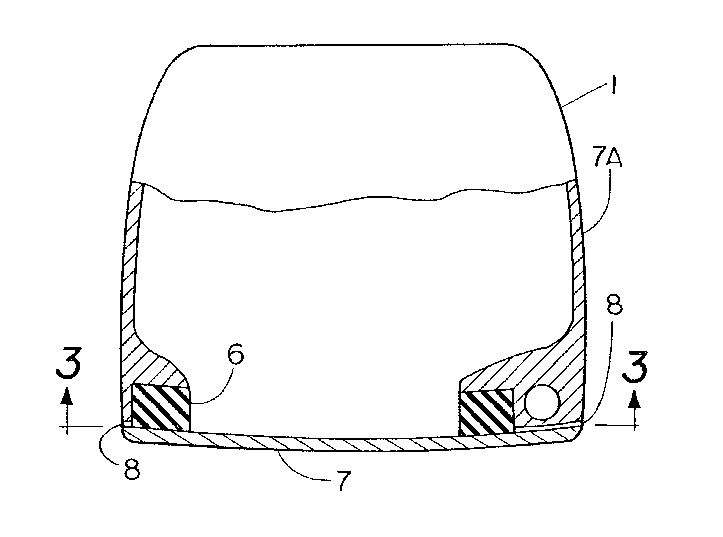
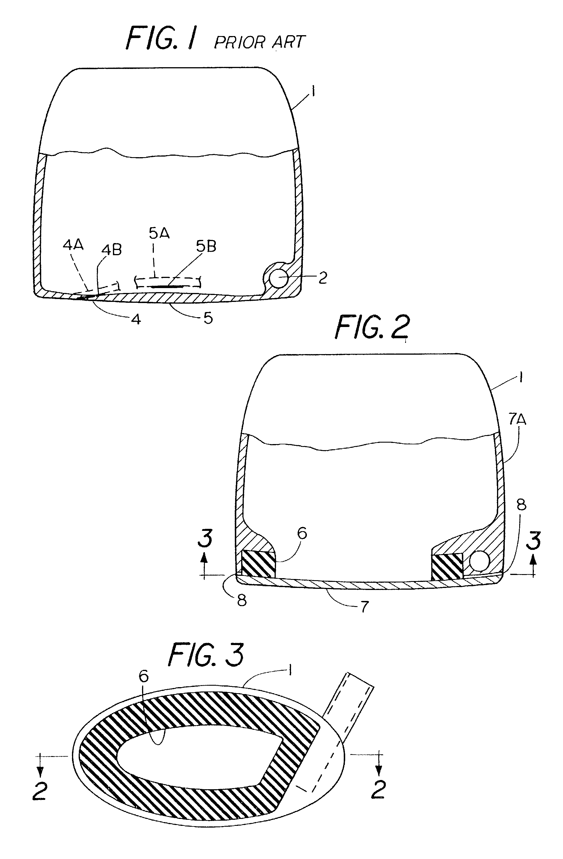
A golf club head is composed of elastic substructures having moderate elasticity and consisting of a face, outer shell, and inner structure in which said elastic substructures that cooperate so as to provide larger impulses to the ball at impact, due to combined elastic properties of the club face for hits at all locations on the face. This allows better distance of shots when loft angle and other design details are appropriately chosen. The structure also minimizes variations of angular orientation of the face surface at the point of impact for all such hits. The elastic substructures can take several forms such as an internal elastic support around the periphery of the face structure, an internal support for the central part of the face structure, and an elastic structure attached to the front side of the face structure, an elastic outer shell, and their combinations. The structure also provides adequate strength, and minimum weight such that a maximum amount of concentrated mass can be located in advantageous places as far as practical from the center of gravity of the head so as to realize maximum moments of inertia about the center of gravity.

Description

[0001] This application refers to and priority is claimed from the United States Provisional Patent Application Ser. No. 60 / 309,888 filed Aug. 3, 2001 and from United States Provisional Application Ser. No. 60 / 348,921 filed Oct. 23, 2001, the contents of both of which applications are incorporated by reference in their entirety.[0002] This invention relates to golf club heads and principally to, but not limited to, wood-type clubs. The principles and designs described can be applied to irons but the need is small since an iron with less loft can always be chosen where extra distance is desired.[0003] Presently, woods are nearly always made with rather stiff materials, using structurally strong and stiff basic face and shell structures and are hollow. Recent designs of woods use a relatively thin metal face such that they have a spring effect giving added shot distance for hits, provided such hits are near the face center. Strong metals are the usual materials of construction of such...

Claims


Application Information

Patent Timeline
Patent Type & Authority Applications(United States)
IPC IPC(8): A63B53/04A63B59/00
CPCA63B53/04A63B59/0092A63B2053/0408A63B2053/0416A63B53/0466A63B2053/0425A63B49/06A63B2053/0454A63B2053/0458A63B60/52A63B60/54A63B53/0425A63B53/0408A63B53/0416A63B53/0454A63B53/0458A63B60/00
Inventor WERNER, FRANK D.GREIG, RICHARD C.
Owner ORIGIN INC
Learn More