Eureka AIR delivers breakthrough ideas for toughest innovation challenges, trusted by R&D personnel around the world.

Device for delivering conditioned air into a passenger area of a rail vehicle

Inactive Publication Date: 2003-04-10
SPEEDINNOV
View PDF0 Cites 2 Cited by
  • Summary
  • Abstract
  • Description
  • Claims
  • Application Information

AI Technical Summary

Benefits of technology

[0005] Therefore, an object of the present invention is to provide a device for delivering conditioned air into a passenger area that remedies those drawbacks, while guaranteeing that air is renewed stably and uniformly in the passenger area so as to offer improved comfort in the passenger area.

Problems solved by technology

However, the Applicant has observed that such an installation suffers from the drawback of being sensitive to differences in flow rate that exist between the feed ducts of the delivery devices disposed on either side of the passenger area, and to any thermal or physical disturbance which tends to unbalance the circulation of air on one side of the vehicle, thereby generating draughts that are unpleasant for passengers.

Method used


Image

  • Device for delivering conditioned air into a passenger area of a rail vehicle
  • Device for delivering conditioned air into a passenger area of a rail vehicle
  • Device for delivering conditioned air into a passenger area of a rail vehicle

Examples


Embodiment Construction

[0018] To make the drawing clearer, only those elements which are necessary to understand the invention are shown. Like elements have like references from one figure to another.

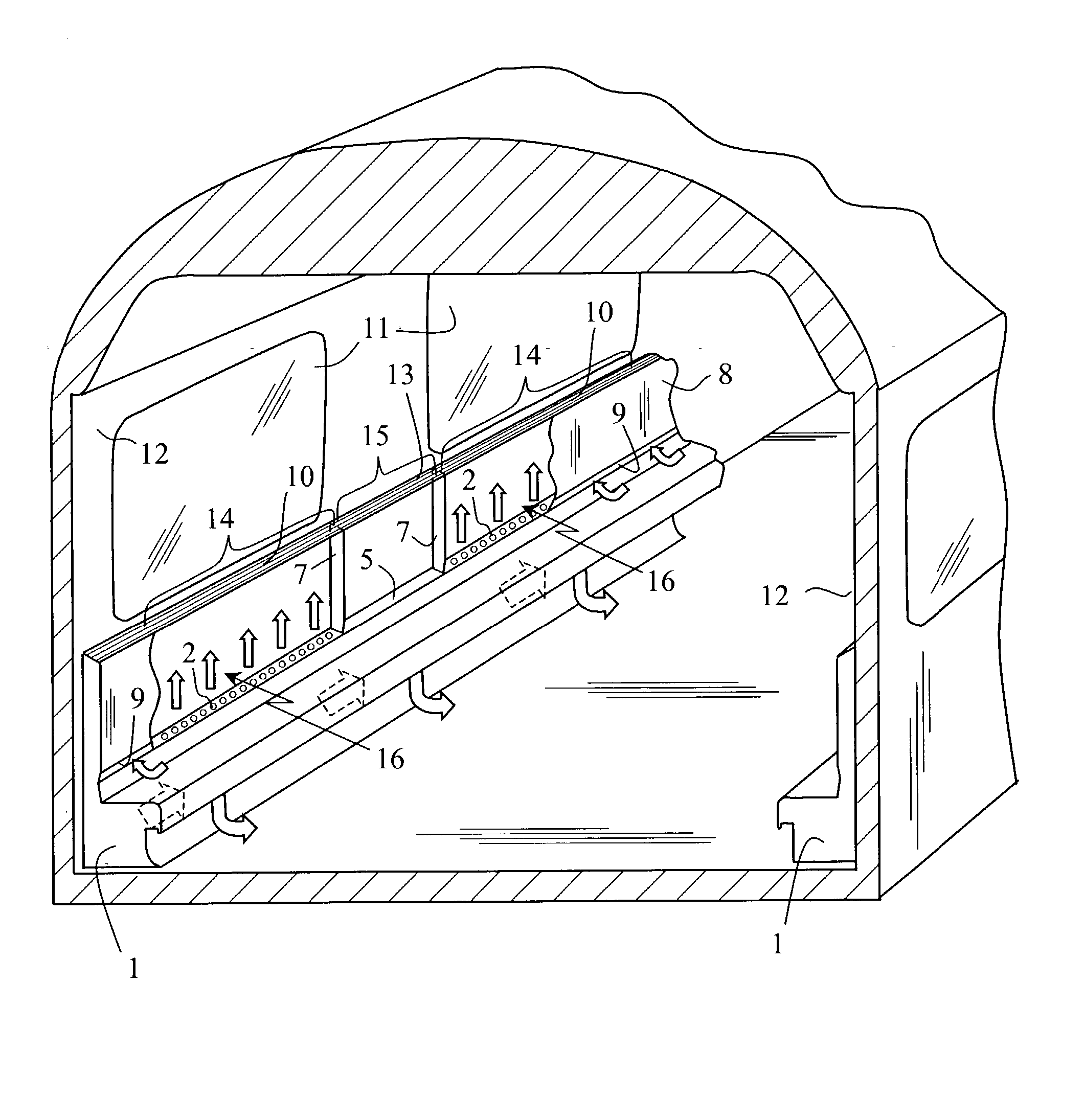
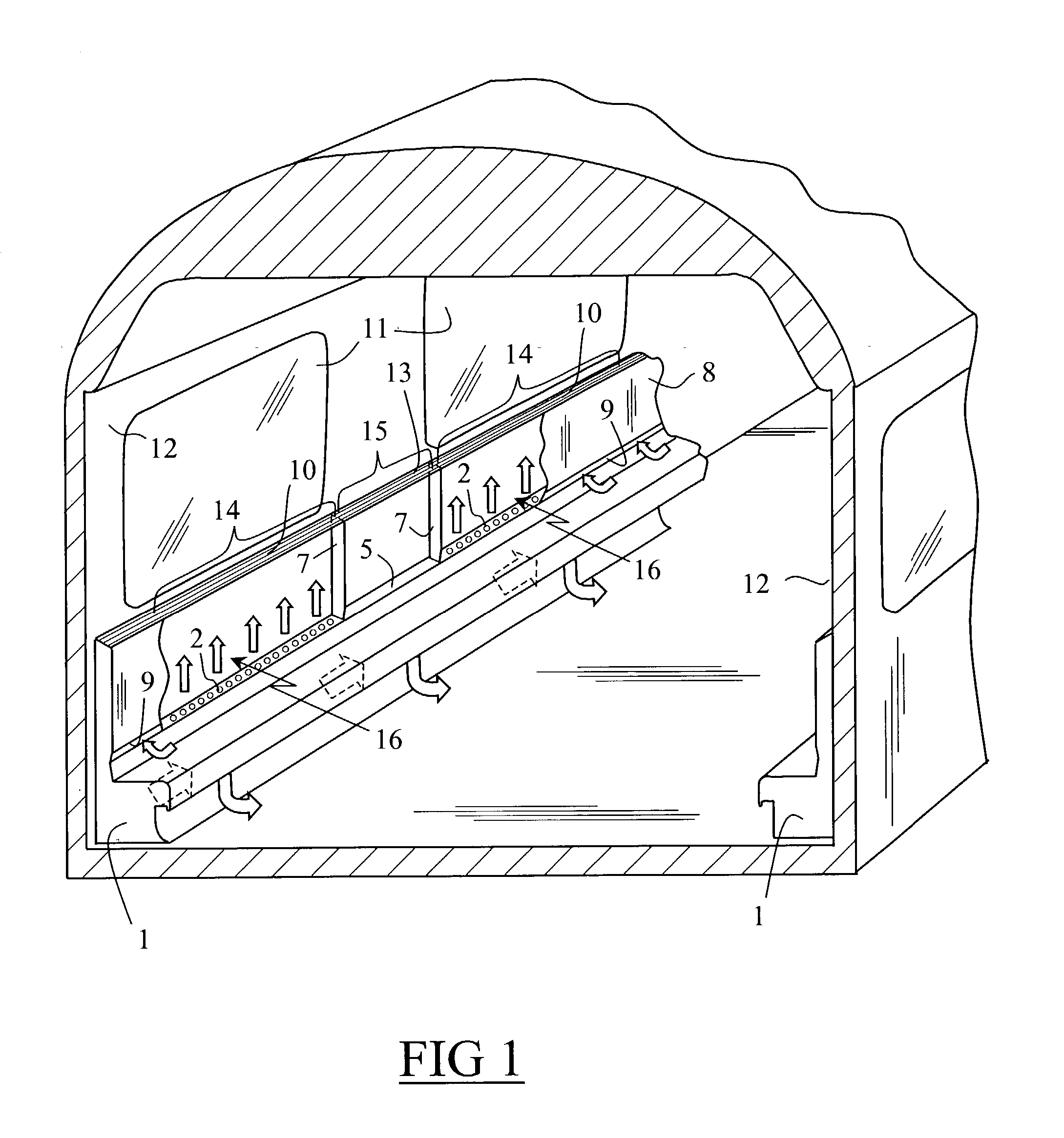
[0019] FIG. 1 shows a rail passenger vehicle having a passenger area designed to seat passengers on a plurality of rows of seats (not shown in the Figures) separated by a central corridor. The passenger area has two side walls 12 provided with windows 11, and, on the bottom portion of each of the walls 12, it receives a respective conditioned air delivery device.

[0020] In the description below, only one conditioned air delivery device is described, since the conditioned air delivery devices at the bottoms of both walls 12 are similar and are disposed symmetrically to each other.

[0021] As shown in FIGS. 1 to 4, the delivery device includes a duct 1 extending along the wall 12, over the entire length of the passenger area, and it is fed by an air-conditioning unit (not shown) which delivers hot air or cold air ...


PUM


Abstract

A device for delivering conditioned air into a passenger area of a rail vehicle, said device comprising a duct extending along the bottom of a side wall of the passenger area, that side face of said duct which is adjacent to the inside of the passenger area being provided with air outlet means disposed over the entire length of the duct and designed so as to release a flow of air across the floor of the vehicle, the top of the duct being provided with openings opening out in a space defined laterally by two substantially parallel walls adjacent to the side wall of the vehicle, said space opening out via its top into the passenger area and its wall that is adjacent to the inside of the passenger area being provided, close to the duct, with one or more slots into which air contained in the passenger area is sucked, wherein said openings are distributed over the length of the duct such that air outlet zones provided with openings are disposed in alternation with barrier zones not provided with any openings, and wherein partitions extending between the parallel walls are disposed where the air outlet zones meet the barrier zones.

Description

[0001] The invention relates to a device for delivering conditioned air into a passenger area of a rail vehicle, the device comprising a duct that extends along the bottom of a side wall of the passenger area and that is provided with distribution means for distributing the air towards the top and the bottom of the side wall, which distribution means include an opening in an intermediate zone, air contained in the vehicle being sucked into the distribution means via said opening.[0002] Document FR-A1-2 632 593 discloses such a device for delivering conditioned air into a passenger area of a rail vehicle. In that device, the duct opens out via its top into a space defined by two parallel walls adjacent to the side wall of the passenger area and extending over the entire length of the passenger area. That space opens out via its top into the inside of the vehicle via gratings that are situated substantially level with the windows of the vehicle. Usually, one such conditioned air deliv...

Claims


Application Information

Patent Timeline
IPC IPC(8): B60H1/00B61D27/00F24F13/068
CPCB60H1/00371B61D27/0018B60H2001/00221
Inventor MINEAUD, GERARDPLICHON, DANIEL
Owner SPEEDINNOV
Why Eureka
Eureka Blog
Learn More