Multi-bolt security door

a security door and multi-bolt technology, applied in the direction of anti-theft devices, wing accessories, hinges, etc., can solve the problems of reducing manufacturing cost and ease of use, reducing the attractiveness of manufacture or use, and incorporating costly locking mechanisms

Inactive Publication Date: 2003-07-31
SZUMINSKI DALE M +1
View PDF16 Cites 12 Cited by
  • Summary
  • Abstract
  • Description
  • Claims
  • Application Information

AI Technical Summary

Benefits of technology

0006] In the present invention, the foregoing purposes, as well as others that will be apparent, are achieved generally by providing a security door comprising a retractable, multiple pin deadbolt bar having a plurality of pins wherein the deadbolt bar is mounted on an interior surface of the door. The deadbolt bar can be operated by an inner or outer door handle. The inner door handle is attached to a shaft having an external screw thread at the distal end, the external screw thread being rotatably engaged with the interior threaded surface of a stabilizer that is attached to the interior surface of the door. The door is attached to the door frame with internally mounted hinges that provide 180.degree. rotation in only one direction, such that the security door may be opened to rest against the wall to which it is attached but may not be pushed in. Further, a security bar is attached to door side panel where the hinges are located to prevent the door from being pulled open even if the hinges have been destroyed or broken.

Problems solved by technology

However, each has a problem in utilization that makes it relatively unattractive to manufacture or use.
For example, some devices incorporate costly locking mechanisms.
Others require complicated mechanical linkages to control the multiple deadbolts that are unique to the disclosed type of door.
Further, none of the prior art doors include additional safety features or features that reduce manufacturing cost and ease of use.

Method used


Image

  • Multi-bolt security door
  • Multi-bolt security door
  • Multi-bolt security door

Examples


Embodiment Construction

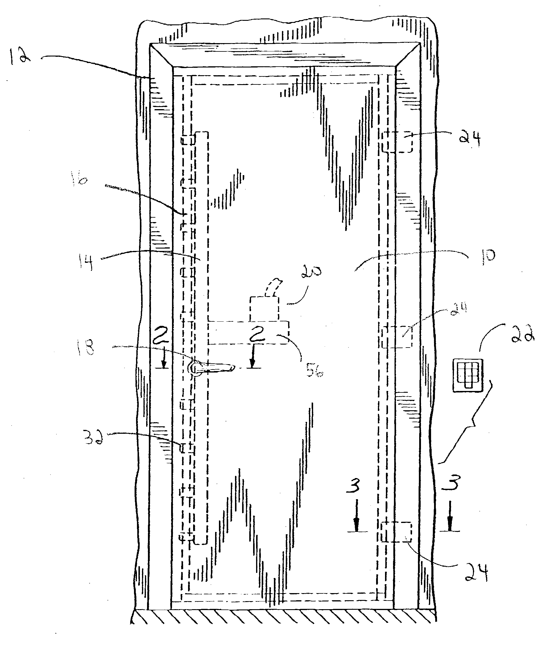
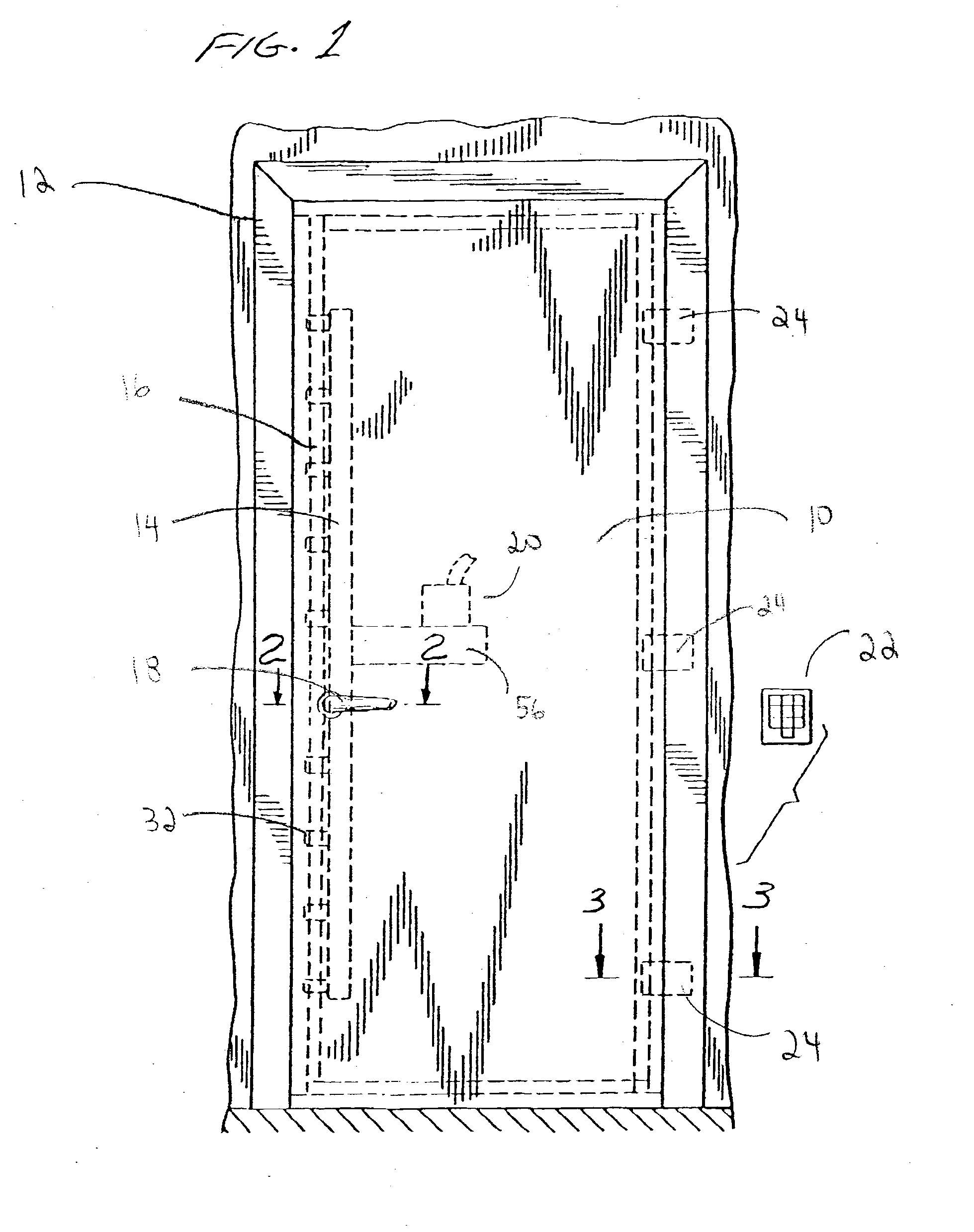
[0022] An improved security door 10 and door frame 12 are generally shown in FIG. 1 from the outside in a closed position. The door 10 generally comprises a retractable deadbolt bar 14 having a plurality of pins 32. Referring to FIGS. 2 and 3, the frame 12 generally comprises a top (not shown), a casing 13, an L-shaped portion 16 and a hinge-mounting portion 76. An L-shaped portion recessed flange 17 and a hinge portion recessed flange 77 prevent the door from being pushed inwards. The door 10 can be locked by extending the deadbolt bar 14 so that the pins 32 extend over the inner (i.e. inside) surface 36 of the L-shaped portion 16 of the frame to prevent the door from opening. See FIG. 2. The deadbolt bar 14 may be controlled by either an inner handle 50 (see FIG. 13) or an outer handle 18. The inner handle 50 is rotatably attached to and supported by a stabilizer 80 that is mounted on the door. See FIG. 5. The deadbolt bar is locked in position by a lock 20 having a retractable to...


PUM


Abstract

A security door having improved security features. The door has a retractable, multiple pin deadbolt bar that can be operated by an inner or outer door handle. The inner door handle has shaft with an external screw thread that allows the handle assembly to be attached to and supported by a stabilizer mounted on the door. The door is attached to a door frame with internally mounted hinges that provide 180° rotation in only one direction such that the door may be opened to rest against the wall to which it is attached but may not be pushed in. A security bar is attached to door side panel where the hinges are located to prevent the door from being pulled out if the hinges broken. The door's lock may be controlled by a remote keypad or wireless device.

Description

PRIORITY CLAIM[0001] This application claims priority from U.S. Provisional Patent Application No. 60 / 352,441 filed on Jan. 28, 2002.[0002] This invention generally relates to a security door having improved security features, and more particularly to a security door comprising a remote-activated, multiple dead-bolt locking assembly that may be used in a wide variety of applications.BACKGROUND OF INVENTION[0003] Doors having enhanced security features, such as multiple locking bolts or pins that simultaneously project from or retract into the door, are well known and have been developed for many specific applications. For example, U.S. Pat. No. 1,094,962 to Arens discloses a hollow metal fire door, U.S. Pat. No. 393,883 to Brown discloses a safe or vault door, and U.S. Pat. No. 992,296 to Titterton discloses spring-actuated locking mechanism for safes or strong rooms. Such security doors utilize complicated configurations of camming grooves, pin followers and pivotally linked bars t...

Claims


Application Information

Patent Timeline
Patent Type & Authority Applications(United States)
IPC IPC(8): E05B47/06E05B63/14E05C19/00E05D3/06
CPCE05B47/0002E05B47/0603E05Y2900/132E05C19/001E05D3/18E05B63/14Y10T70/5978Y10T70/713
Inventor SZUMINSKI, DALE M.STEPP, RICHARD E.
Owner SZUMINSKI DALE M
Why Eureka
Try Eureka