Marking instruments and methods of manufacturing marking instruments

a technology of marking instruments and marking tools, which is applied in the field of marking instruments, can solve the problems of increasing fatigue and "writer's cramp", difficulty in storage of writing and marking instruments in non-rigid small spaces, and presenting a potential danger to users, especially children

Inactive Publication Date: 2003-07-31
STEINSCHADEN ANDRE R
View PDF35 Cites 17 Cited by
  • Summary
  • Abstract
  • Description
  • Claims
  • Application Information

AI Technical Summary

Problems solved by technology

The typical length, volume and rigidity of a writing and marking instrument make it difficult for a writing and marking instrument to be stored in non-rigid small spaces, such as a wallet, or a pocket which is part of the user's clothing.
The generally narrow rigid cylindrical form offers only a limited contact surface for the user's hand, increasing the potential for fatigue and "writer's cramp" with prolonged continuous use.
The rigidity results in the writing and marking instrument presenting a potential danger to th

Method used


Image

  • Marking instruments and methods of manufacturing marking instruments
  • Marking instruments and methods of manufacturing marking instruments
  • Marking instruments and methods of manufacturing marking instruments

Examples


embodiment 76

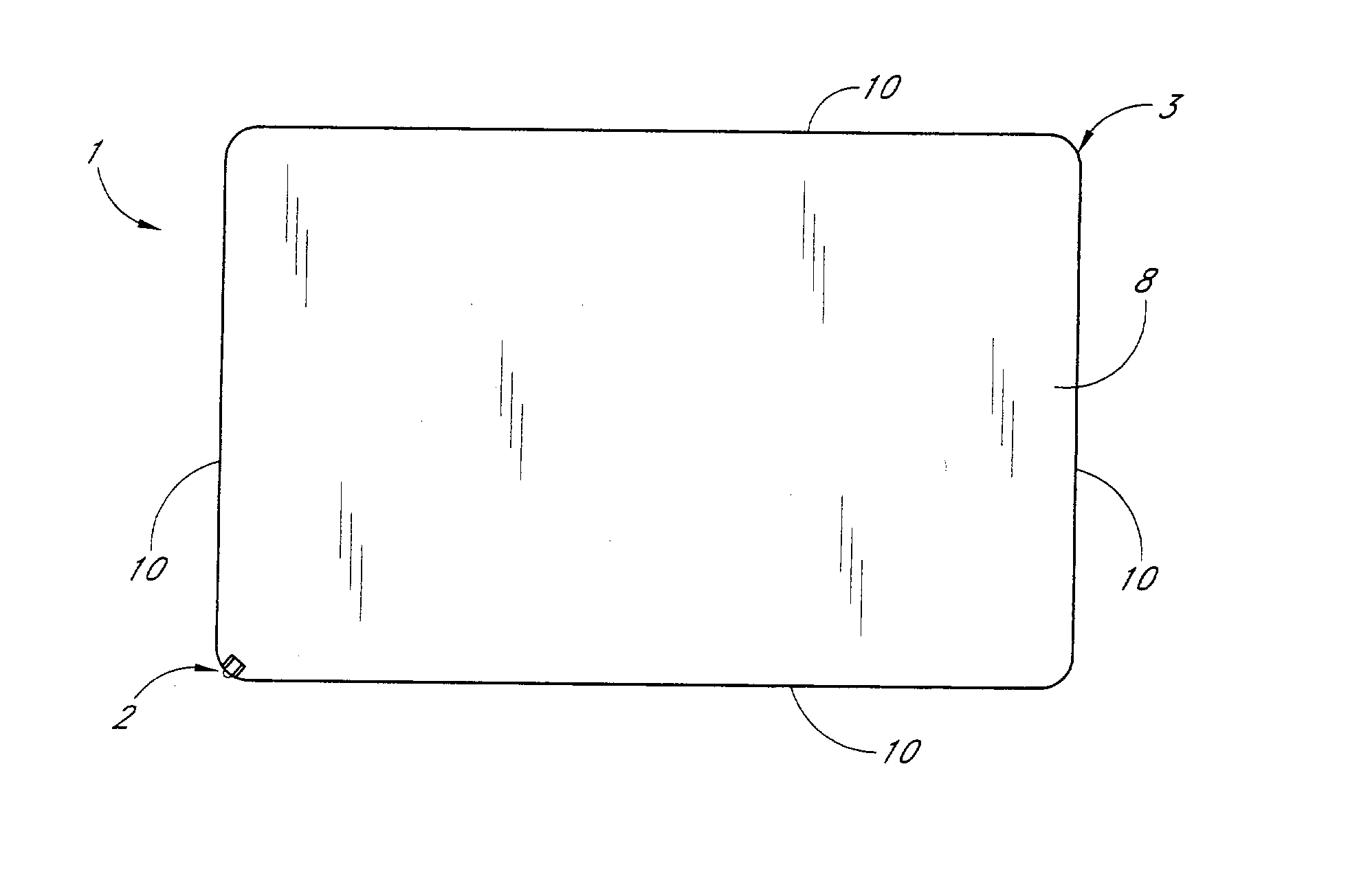
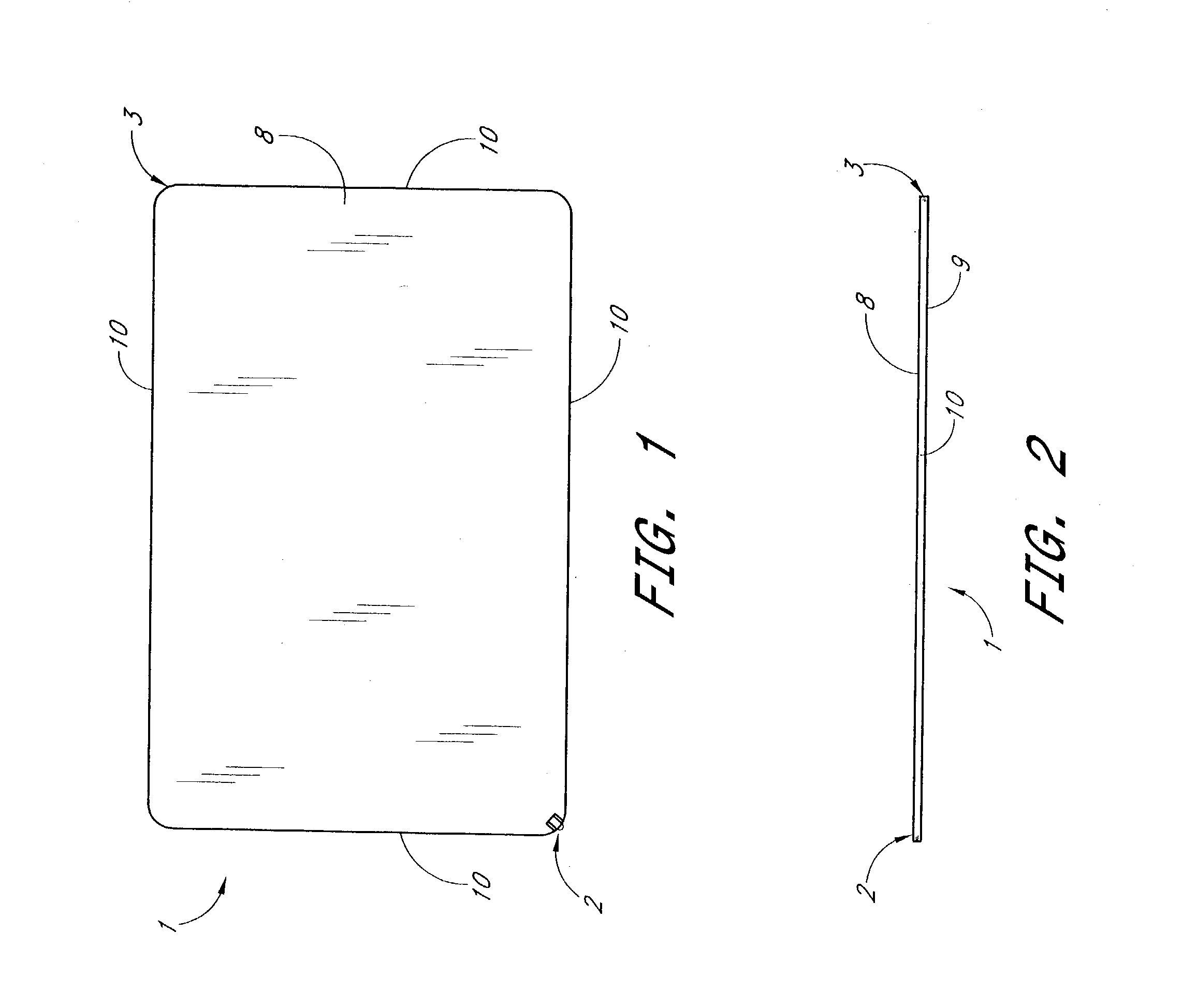
[0085] Some or all of the edges of the body can be suitably rounded to provide a more ergonomic shape and feel which increases user comfort during marking. FIG. 6 shows an enlarged side edge perspective view of a card corner containing a marking device 2 with both straight edges 12, which are leading away from the corner arc of the body, being of a rounded form. The body edges can be rounded in the injection molding manufacturing method by using a molding die that has rounded edges in the molding cavity. In the lamination manufacturing method the body edges can be rounded by using a suitable forming die with rounded edges, or by milling the edges round. Alternatively, a rounded edge can be formed by adding a suitable rounded material, such as a convex molding, to the edges of the body. This rounded material can be attached to the body using various methods, such as laminating using heat, adhesives such as commercially available epoxies and glues, coatings, lasers, or other suitable ...

embodiment 38

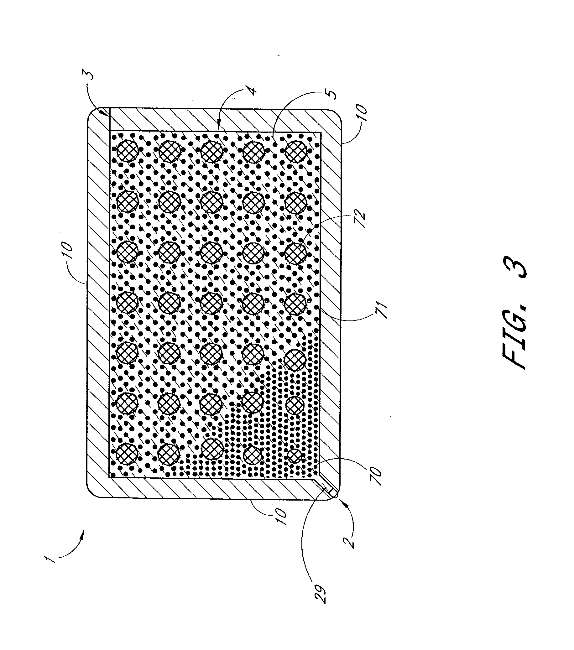
[0102] Alternatively, the marking substance-containing apparatus can be in the form of a reservoir-like chamber which is tube-like and resembles a refill. Such a tube-like chamber can be made of a suitable material, such as an extruded plastic, and can be attached to the marking device, such that it is in fluid communication with it. Such a tube-like chamber can also contain an ink follower made of a suitable material, which ensures flow of the marking substance to the marking device. FIG. 12 shows an embodiment of a marking instrument containing a marking device 2a attached to a tube-like marking substance-containing apparatus 4a which is partially filled with a marking substance 5. FIG. 12 also shows a venting apparatus 3. FIG. 29 shows a coin-like embodiment 38 containing the same elements as FIG. 12.

[0103] Alternatively, the marking substance-containing apparatus can be in the form of a reservoir-like chamber which is bag-like and contains the marking substance in a sealed manne...


PUM


Abstract

A handheld marking instrument includes a body having a substantially flat shape, a first chamber formed within the body and having an inner surface configured to receive and contain a marking substance within the body, and a first marking device configured to deliver the marking substance to a desired surface during marking. The first marking device is incorporated in the body and in communication with the first chamber to access the marking substance contained by the inner surface. At least a part of the first marking device is moveable between an exposed position for marking on the desired surface, and a retracted position. In one embodiment, the body has a form factor of a financial transaction card.

Description

[0001] 1. Field of the Invention[0002] The present invention relates to a marking instrument.[0003] 2. Description of the Related Art[0004] Marking instruments of all types, three-dimensional shapes, and sizes exist, and may be used for writing and marking on a desired surface. The most common form for a marking instrument is a rigid extended cylindrical shape of varying length and diameter, containing an apparatus to contain a marking substance and / or solid (hereinafter referred to as a "marking substance-containing apparatus"), and an apparatus to suitably deliver the marking substance and / or solid (hereinafter referred to as a "marking substance") to the surface to be written upon or marked (hereinafter referred to as a "marking device" or a "marking solid-delivering apparatus").[0005] Generally, such writing and marking instruments also contain an apparatus to prevent the marking device and / or the marking solid-delivering apparatus from marking surfaces when the writing and mark...

Claims


Application Information

Patent Timeline
IPC IPC(8): B43K3/00B43K5/00B43K7/00B42D15/10B43K7/02B43K7/12B43K23/08B43K29/00B43K29/093G06K19/00G06K19/06
CPCB43K5/005B43K7/005B43K29/00B43K8/003B43K21/006B43K7/12
Inventor STEINSCHADEN, ANDRE R.
Owner STEINSCHADEN ANDRE R
Why Eureka
Try Eureka