Dust mop handle method and apparatus

a technology of dust mop and handle, which is applied in the field of dust mop handle method and apparatus, can solve the problem of not finding any handle or method for dust mop

Inactive Publication Date: 2003-08-14
BIGGS BLYTH S
View PDF0 Cites 35 Cited by
  • Summary
  • Abstract
  • Description
  • Claims
  • Application Information

AI Technical Summary

Problems solved by technology

Also, I have been unable to find any handle or method for dust mops which anticipate nor suggest what is set forth in this application.

Method used


Image

  • Dust mop handle method and apparatus
  • Dust mop handle method and apparatus
  • Dust mop handle method and apparatus

Examples


Embodiment Construction

[0021] An inventory of items in the drawings with reference numerals is:

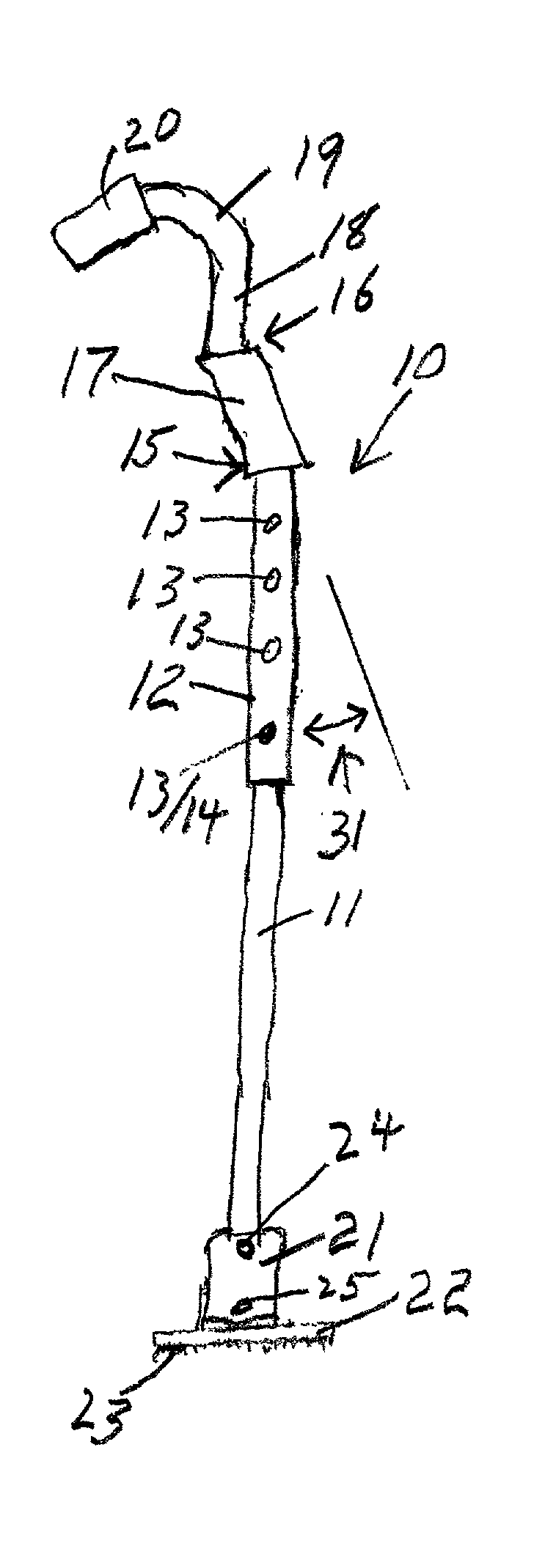
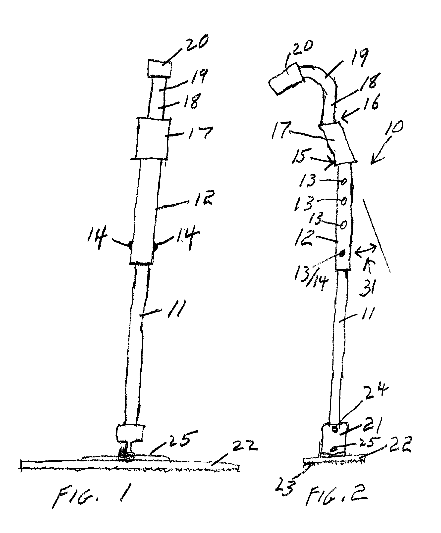
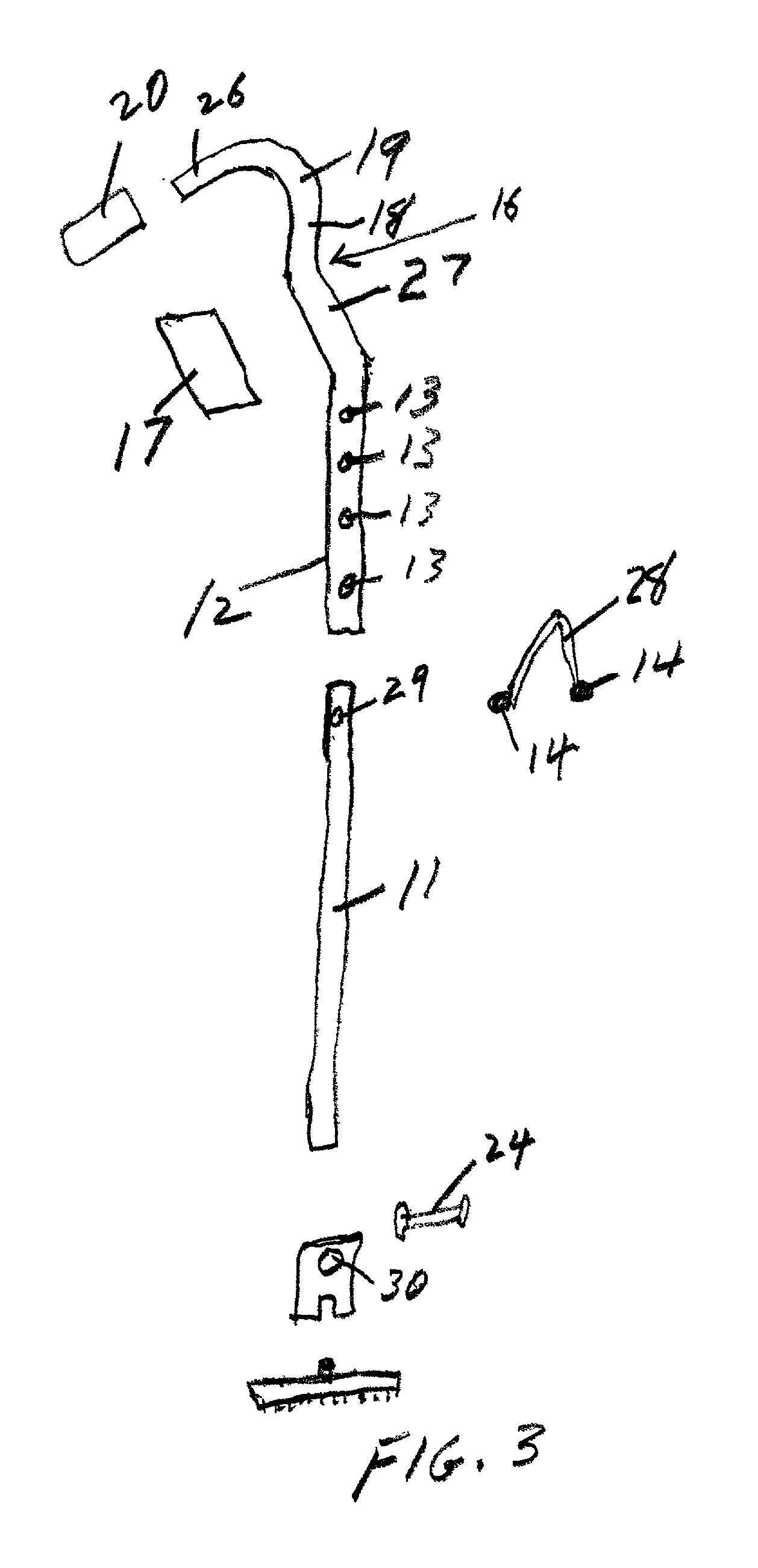
1 Numeral Item 10 handle generally 11 straight telescoping inner segment 12 straight telescoping outer segment 13 adjustment holes 14 ball 15 curve 16 curve 17 grip sleeve 18 straight segment 19 curve 20 grip 21 connector sleeve 22 dust mop carrier 23 dust mop yarns 24 rivet 25 mop hanger rod 26 straight segment 27 straight segment 28 spring 29 hole 30 hole

[0022] A handle generally 10 made of any suitable material (I prefer aluminum tubing, although any other material, including, without limitation, wood or plastic which can be shaped as described below and shown in the drawing may be used) is composed of a straight segment 11 having two opposed holes 29 (only one is visible). An essentially "V" shaped spring element 28 has two balls or protrusions 14 and is inserted into the hollow segment 11 in such manner that the balls or protrusions 14 protrude through the two holes 29. When the inner telescoping segment 11...


PUM


Abstract

This is a dust mop handle and method in which the handle has a plurality of arcuate and straight segments including means to attach a dust mop to one end; unique hand holding means providing for bi-planar holding and movement of the dust mop handle in such manner that the effective force being applied to the dust mop is multiplied and enhanced and strain on the user is reduced.

Description

CROSS REFERENCE TO RELATED PATENT APPLICATIONS[0001] This application may be considered to be related to my presently pending application for Utility Tool Handle, Ser. No. ______, filed Jan. 31, 2002.[0002] I. Field of the Invention[0003] This invention is in the general field of dust mops and the like;[0004] The invention is more particularly in the field of handles for, and methods of using, dust mops and the like which must be manipulated at a distance from the user while at the same time reducing strain and the like by the use of ergonomic principles which maintain essentially in-line pressure with the user's hands, arms, and shoulders and the like.[0005] II. Description of the Prior Art[0006] I am very familiar with this field and have made several inventions and received patents on handles. Also, I have studied literature in the field, patent files, and commercially available items. While there have been many extension handles and the like for various implements, I have recent...

Claims


Application Information

Patent Timeline
Patent Type & Authority Applications(United States)
IPC IPC(8): B25G1/04B25G1/10
CPCB25G1/102B25G1/04
Inventor BIGGS, BLYTH S.
Owner BIGGS BLYTH S
Why Eureka
Try Eureka