Optical disk device

a technology of optical disk and optical disk, which is applied in the direction of digital signal error detection/correction, instruments, recording signal processing, etc., can solve the problems of reducing the reflected light intensity to a constant level and failing to achieve stable recording quality

Inactive Publication Date: 2003-08-28
TEAC CORP
View PDF10 Cites 14 Cited by
  • Summary
  • Abstract
  • Description
  • Claims
  • Application Information

AI Technical Summary

Benefits of technology

[0009] FIG. 10 shows an example of change in the .beta. value generated when data is recorded while adjusting the recording power in accordance with the above equation (2). While the target .beta. value .beta.o can be attained at the inner portions of the disk proximate to the PCA area, the .beta. value exceeds the target value .beta.o at the disk outer peripheral portions, because of excessive adjustment (compensation) of the recording power. This indicates that the assumption B / P=constant does not always hold true, and that adjustment of recording power should be performed in accordance with some other appropriate relationship.

Problems solved by technology

However, after a while when the pit is formed, diffraction by the formed pit reduces the reflected light intensity to a constant level.
Although the recording power P is thus conventionally adjusted under the assumption that the .beta. value can be maintained at a constant value by employing the relationship B / P=constant, there frequently exist cases where such adjustment cannot actually maintain a constant .beta. value over all regions of an optical disk, failing to achieve stable recording quality.

Method used


Image

  • Optical disk device
  • Optical disk device
  • Optical disk device

Examples


Embodiment Construction

[0028] An embodiment according to the present invention is next described by referring to the drawings.

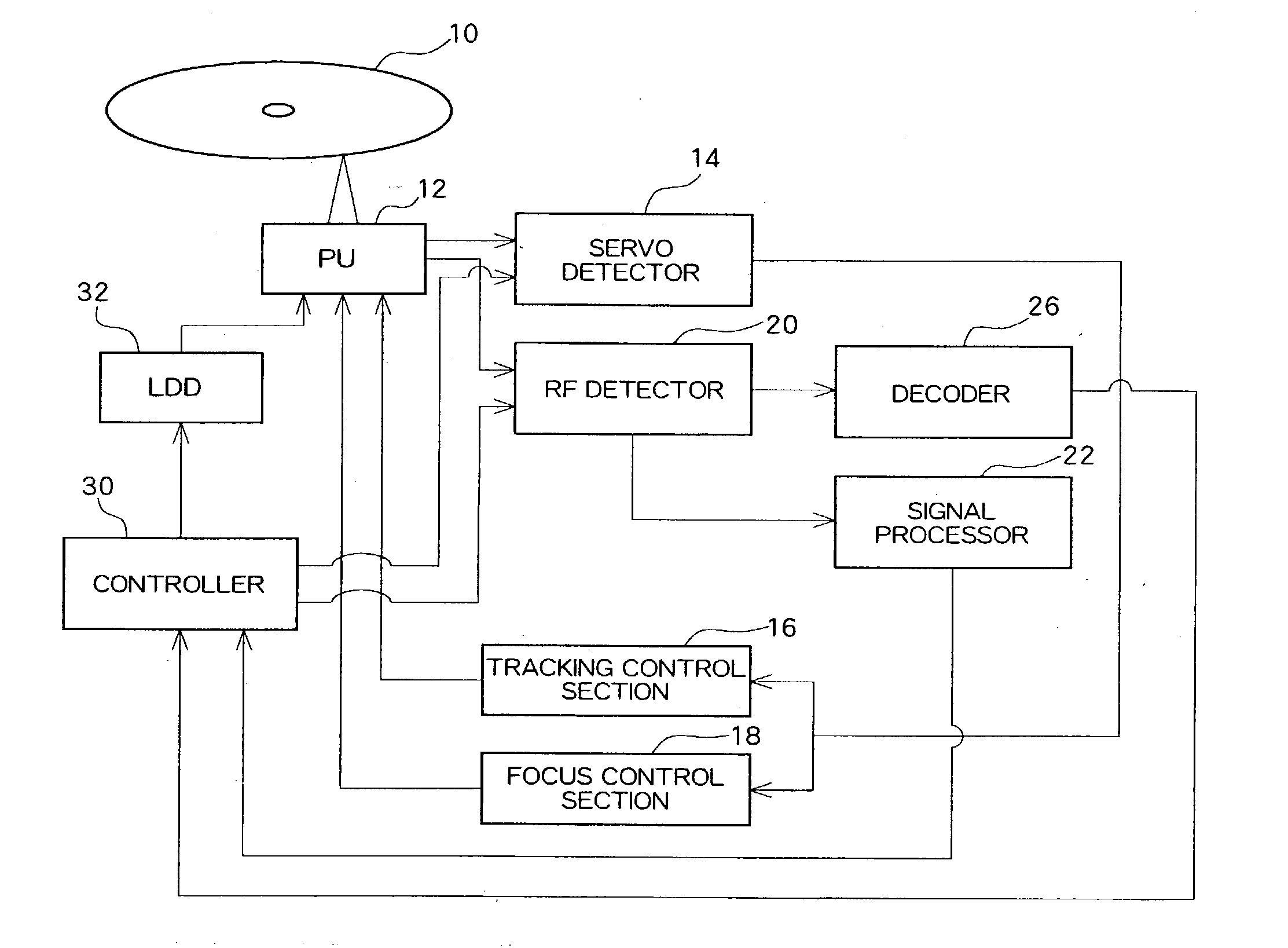
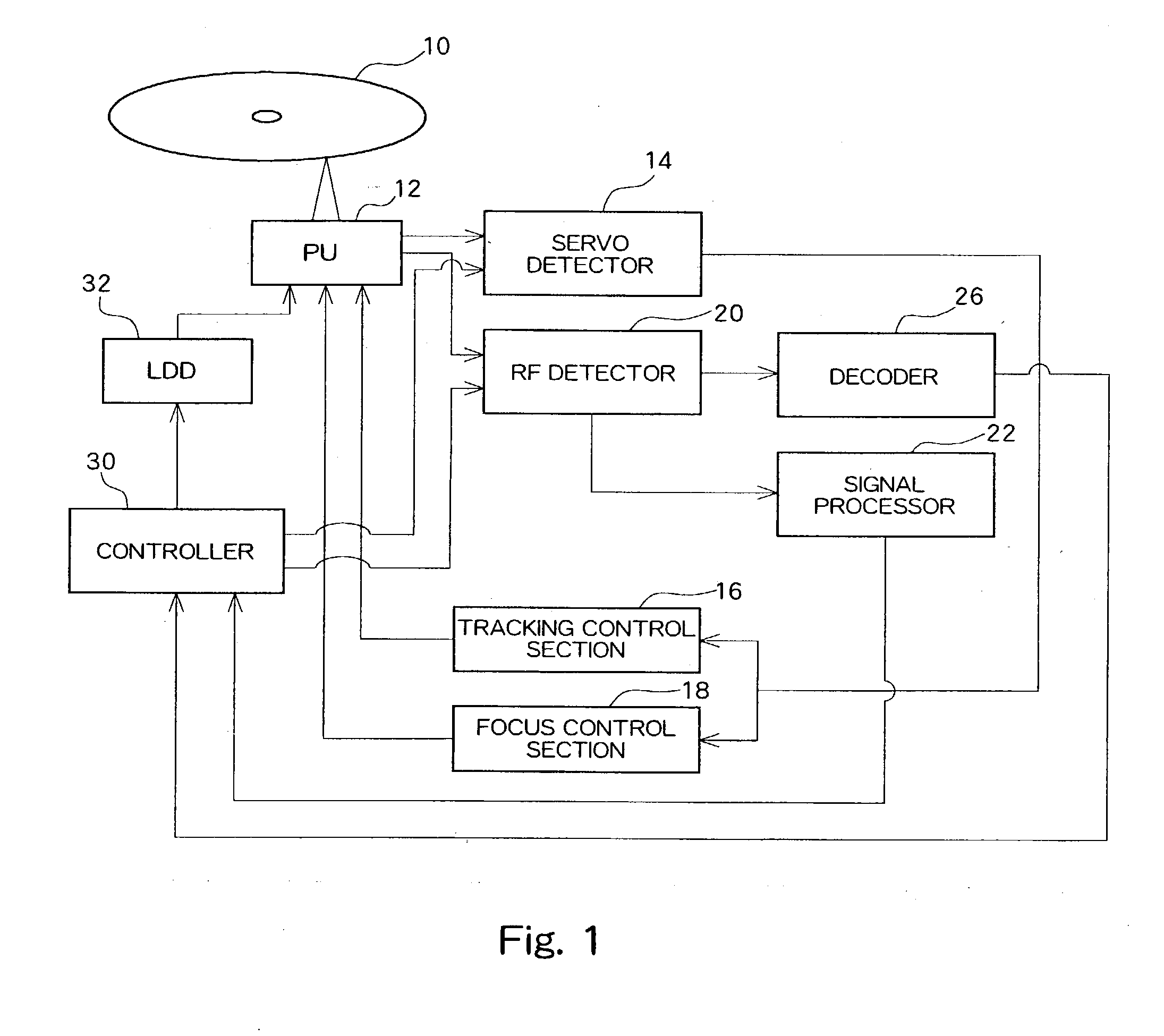
[0029] FIG. 1 is a block diagram showing a configuration of an optical disk device according to an embodiment of the present invention. A recordable optical disk 10, which may be a CD-R / RW or DVD-R / RW, is driven in rotation by a spindle motor.

[0030] A pickup (PU) 12 is provided opposing the optical disk 10. The pickup 12 includes a laser diode (LD) which irradiates a laser beam on the surface of the optical disk 10. The laser diode is driven by a laser diode driving circuit (LDD) 32 to irradiate a laser beam at a reproducing power level when reproducing data, and a laser beam at a recording power level when recording data (reproducing power level < recording power level). The pickup 12 further includes a photodetector which converts the reflected laser light from the optical disk 10 into an electrical signal. The reproduced signal is supplied to a servo detector 14 and an RF detect...


PUM

PropertyMeasurementUnit
recording poweraaaaaaaaaa
recording speedaaaaaaaaaa
poweraaaaaaaaaa

Abstract

The present invention provides an optical disk device which optimizes recording power level used when recording data. A controller records test data in a test region of an optical disk and evaluates reproduced signal quality of the test data, so as to determine an optimum recording power level Po (OPC). Subsequently, the controller uses reflected light intensity level B obtained when recording data to make adjustments to the optimum recording power level Po, thereby obtaining recording power level P. The recording power level P is adjusted such that Bm / Pn=constant, where m and n are positive rational numbers satisfying m<n. When m=1, the value of n is greater than or equal to 1.5 and no larger than 10.

Description

[0001] 1. Field of the Invention[0002] The present invention relates to an optical disk device, and more particularly to optimization of power level for recording data.[0003] 2. Description of the Related Art[0004] In an optical disk device such as a CD-R / RW drive and a DVD / R drive which allows recording of data, Optimum Power Control (OPC) and Running Optimum Power Control (ROPC) techniques are employed to optimize recording power level when recording data. OPC refers to a process in which test data are recorded (test-writing) on a predetermined area (PCA area) of an optical disk, and reproduced so as to determine a recording power level at which a value indicating reproduced signal quality, such as the .beta. value, achieves a target value. ROPC refers to feedback control performed with respect to the recording power level such that the intensity of reflected light from the optical disk during recording of data is maintained at a constant level. This control is executed to overcom...

Claims


Application Information

Patent Timeline
Patent Type & Authority Applications(United States)
IPC IPC(8): G11B7/00G11B7/0045G11B7/007G11B7/125G11B7/1263G11B7/1267
CPCG11B7/00736G11B7/1267G11B7/1263G11B7/004
Inventor OGAWA, TOSHIHIRO
Owner TEAC CORP
Why Eureka
Try Eureka