Cleaning system

a fan and cleaning system technology, applied in the direction of piston pumps, pump components, non-positive displacement fluid engines, etc., can solve the problems of fan major downtime and maintenance, and achieve the effect of eliminating down time and inefficiency, high velocity, and more adjustment of crank rod length

Inactive Publication Date: 2007-07-19
PACE EDGAR ALAN
View PDF11 Cites 13 Cited by
  • Summary
  • Abstract
  • Description
  • Claims
  • Application Information

AI Technical Summary

Benefits of technology

[0007] The present invention is a cleaning system having a high velocity fan held within an air-directing casing movably mounted between the lower ends of an inverted U-shaped yoke. A blade structure within the casing assures that air is directed outwardly in a narrow beam. The system rotates as a whole about a vertical extendable support trube and the casing and fan oscillate about a horizontal axis through a vertical sweep angle which can extend from horizontal to near-vertical, both in the upper and lower direction. A crank arm is connected to the U-shaped yoke and to one end of a crank rod which, in turn, connects with the fan casing. Rotation of the crank arm displaces the crank rod so that casing and fan oscillate about the horizontal axis where the casing is held by the inverted yoke lower ends. The crank arm has spaced apart holes to provide adjustment in the effective length of the crank rod. More adjustment in the length of the crank rod is obtained by using a two piece crank rod with the free end of each crank rod piece adjustably secured to a connecting rod. Thus the length of the crank rod can be changed as needed without the need of replacing it with a crank rod of a different length thus eliminating the down time and inefficiency occurring when the existing crank rod is removed and another crank rod of a different size is installed. One or more extendable sway braces may be used in the support structure, so that the support tube, the sway braces and the cronk rod can all be adjustably changed without removing and replacing them. A newly designed crank arm having additional spaced apart holes adds additional adjustability features.
[0010] Still another objective of the present invention is to provide an adjustable support rod and one or more adjustable sway braces to be certain that the entire structure can be changed consistently with a change in the length of the crank rod.

Problems solved by technology

Air blast fans have, for the most part, been effective in keeping lint collection off machinery, ceilings and floors especially when they are placed in groups with other fans, however they are limited to an area or pattern where cleaning takes place because of the structure on which they are positioned.
However when a more deliberate, different pattern is desired, the crank rod will need to be changed to a different length thus requiring major down and maintenance on the fan.

Method used


Image

  • Cleaning system
  • Cleaning system
  • Cleaning system

Examples


Embodiment Construction

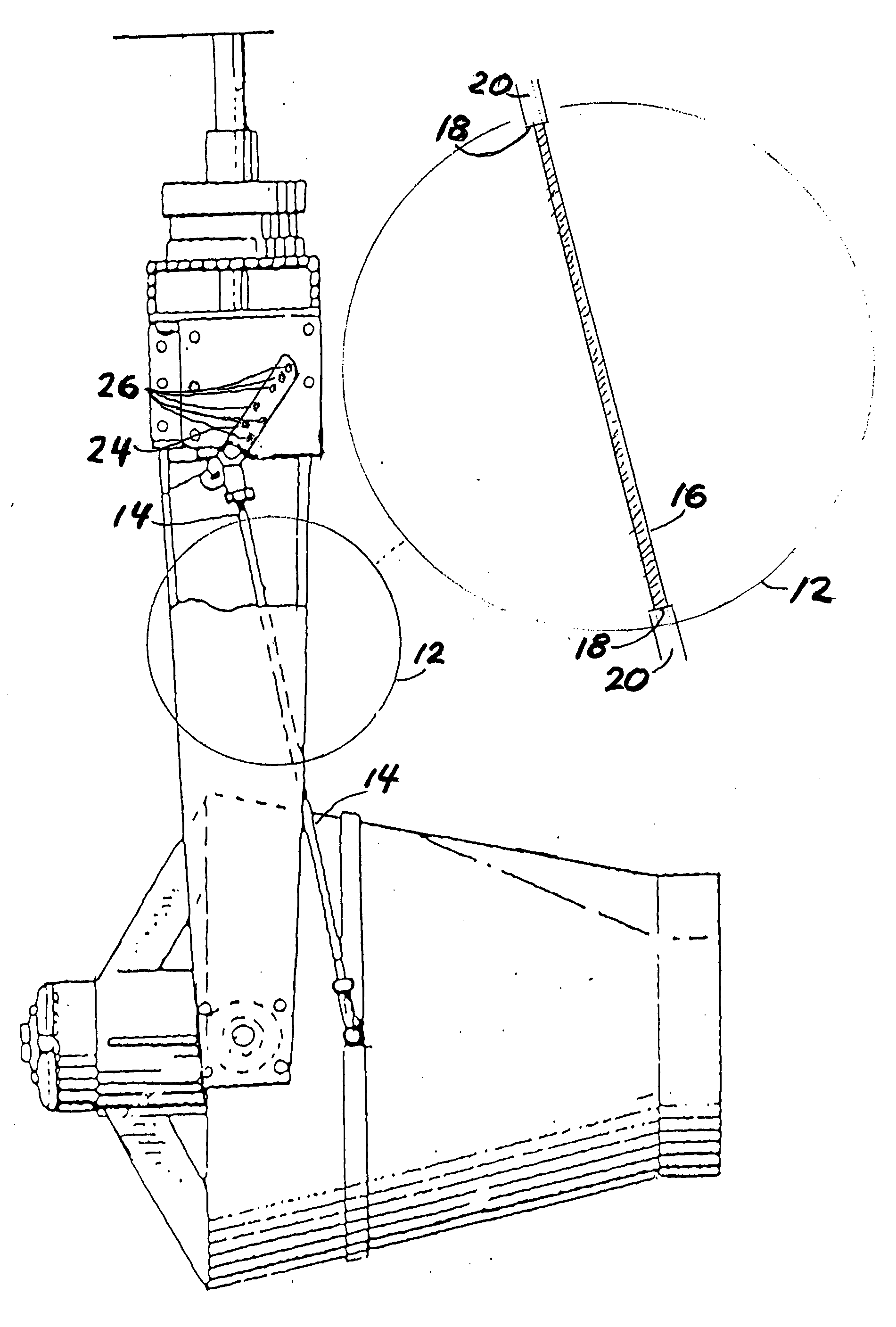
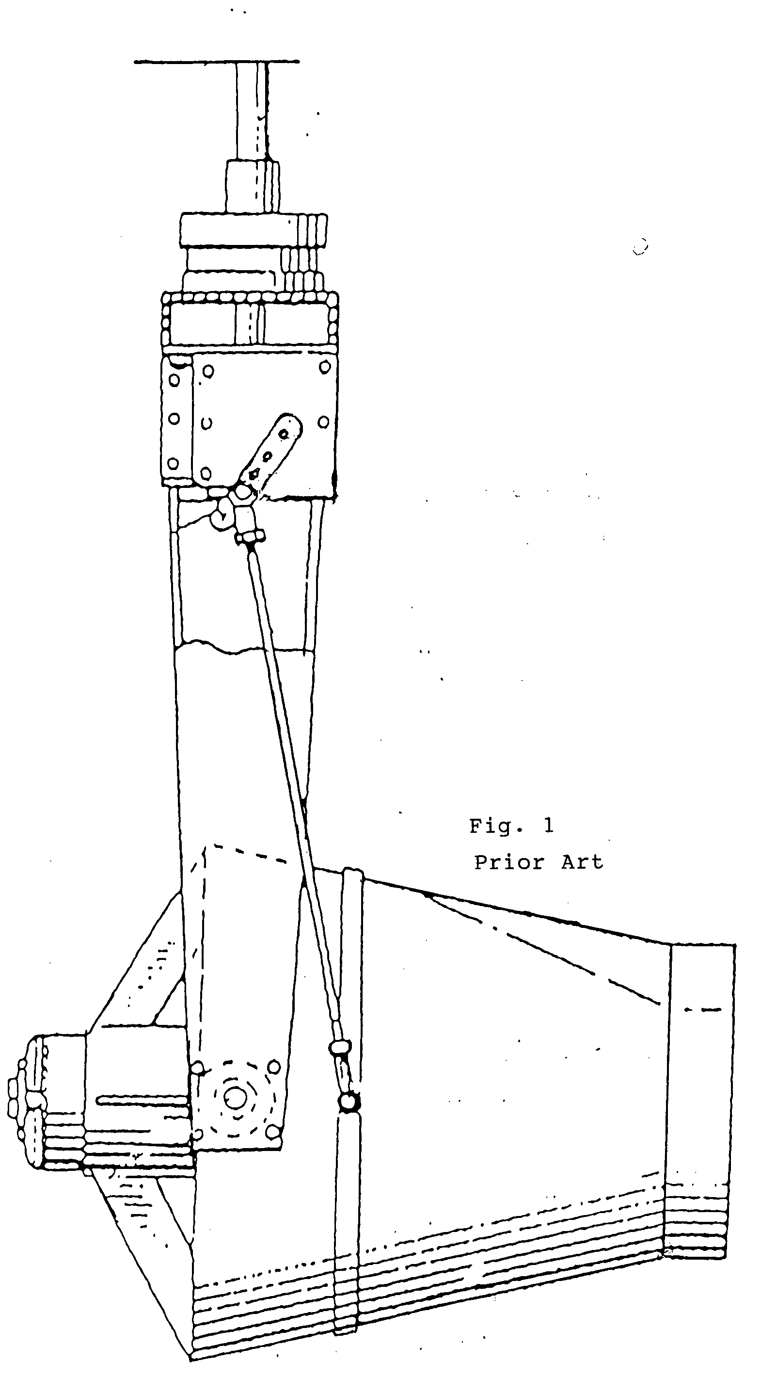
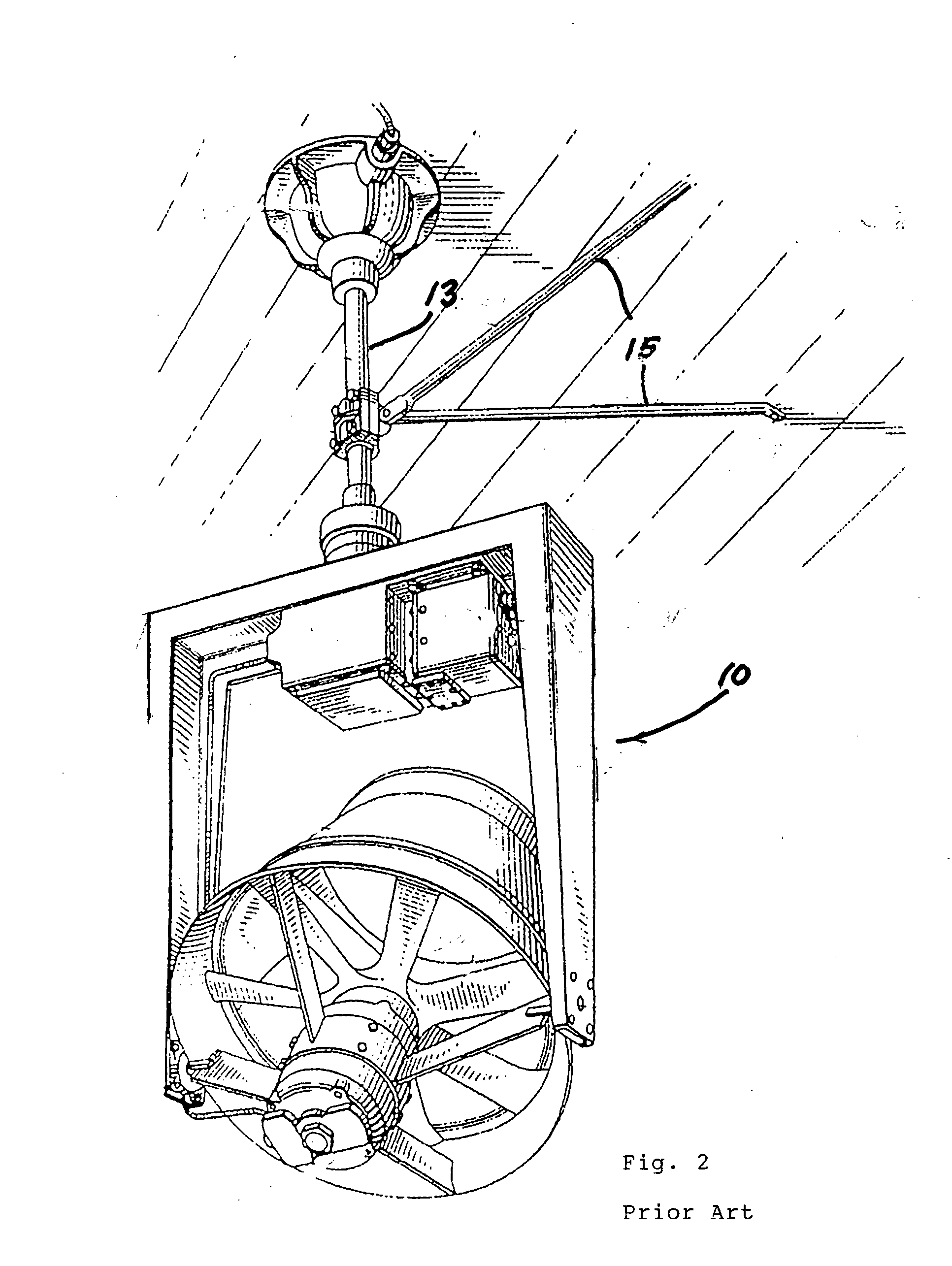
[0027] Referring now to the drawings, the present invention involves improvements in and for the ceiling cleaner fan 10 shown in FIGS. 1 and 2 which is used to control lint accumulation on the ceilings, walls, floors and machinery in textile mills, laundries and other facilities where fabrics and the like are fabricated, used or otherwise handled. Fan 10 is universally mounted and of the type that rotates as a whole about a vertical axis while the fan itself simultaneously oscillates about a horizontal axis so that the air stream from the fan oscillates through a vertical sweep angle which can extend from horizontal to near-vertical. The particulars of cleaner fan 10 and its associated components are set forth in U.S. Pat. No. 3,072,321, the contents of which are incorporated herein by reference.

[0028] In the improved version of fan 10 (hereinafter 10′) and its components, a more precise, regulated and efficient control system has been developed to maximize the positive utilization...


PUM


Abstract

A cleaning system has a high velocity fan held within an air-directing casing movably mounted between the lower ends of an inverted U-shaped yoke. The blade configuration of the fan assures that air is directed outwardly in a narrow beam. The system rotates about a vertical extendable support tube and the casing and fan oscillate about a horizontal axis through a vertical angle which can extend from horizontal to near-vertical in the upper and lower direction. A crank arm connects to the U-shaped yoke and to one end of a crank rod which connects to the fan casing. Rotation of the crank arm displaces the crank rod so that the casing and fan oscillate about the horizontal axis. The crank arm is adjustable in length by spaced apart holes. The length of the crank rod is adjustable by using a two piece crank rod with the free end of each crank rod piece being adjustably secured to a connecting rod. The newly designed crank rod having additional spaced apart holes provides additional adjustability features.

Description

BACKGROUND OF THE INVENTION [0001] 1. Field of the Invention [0002] The present invention relates to universally mounted fans and more particularly to an improved construction for such fan use in textile mills, laundries or any other operation where removing lint from ceilings, walls, floors and machinery is desired. [0003] 2. Description of the Prior Art [0004] Lint accumulation in textile mills and laundries on machinery, ceilings and walls is to be avoided wherever possible. Air blasts and traveling cleaners have been extensively used for this purpose, and some cleaners have been specifically designed for sweeping floor and aisle areas. [0005] Air blast fans have, for the most part, been effective in keeping lint collection off machinery, ceilings and floors especially when they are placed in groups with other fans, however they are limited to an area or pattern where cleaning takes place because of the structure on which they are positioned. They can be programmed to cut off whe...

Claims


Application Information

Patent Timeline
Patent Type & Authority Applications(United States)
IPC IPC(8): F04B17/00
CPCF04D29/601F04D25/088
Inventor PACE, EDGAR ALAN
Owner PACE EDGAR ALAN
Why Eureka
Try Eureka