Auger for boring and weeding

a technology for boring and weeding, applied in the field of augers, can solve the problems of unsatisfactory requirements, relatively high cost of recognized solutions, and achieve the effect of simple manufacturing and assembly

Inactive Publication Date: 2006-01-19
MOTOSKO THOMAS P
View PDF36 Cites 12 Cited by
  • Summary
  • Abstract
  • Description
  • Claims
  • Application Information

AI Technical Summary

Benefits of technology

[0012] By way of summary, the present invention is directed to an auger which is both lightweight and durable. One object of the invention is to provide an apparatus that can be used in a standing or sitting position and can be used with a variety of power tools. Another object of the invention is to provide an apparatus that has one or more of the characteristics discussed above but which is relatively simple to manufacture and assemble using a minimum of equipment and is relatively inexpensive.
[0013] In accordance with one aspect of the invention, these objects are achieved by providing an apparatus comprising a shaft having a first end and a second end. The first end of the shaft contains a hexagonal shape portion and the second end includes a pointed tip which is offset from center and has one flat side at a preferred angle. A disc is attached a distance from the second end. In another embodiment, a second or extension shaft is provided which is longer than the first. The second shaft has a first end and a second end. Located at the first end is a hexagonal shaped portion. At the second end there is a first shaft receiving portion with the bore therethrough. The first shaft is attached to the second shaft by a shaft locking device or pin. Having a first shaft and a second shaft allows versatility of use with different types of power tools. Moreover, it also allows the user to use the auger in both a kneeling or sitting position and a standing position. Another object of the invention is to provide a method that has one or more of the characteristics discussed above but which is relatively simple to set up and operate.
[0016] In accordance with still another aspect of the invention, the second shaft has a plurality of holes near the second end. This allows the user to adjust the height of the tool more acutely when the first and second shafts are connected.

Problems solved by technology

However, a previously recognized problem has been that such augers are specifically usually manufactured for use with one device or the other.
Heretofore these requirements have not been fully met without incurring various disadvantages.
Previously recognized solutions also have the disadvantage of relatively high cost.

Method used


Image

  • Auger for boring and weeding
  • Auger for boring and weeding
  • Auger for boring and weeding

Examples


Embodiment Construction

[0041] The present invention and the various features and advantageous details thereof are explained more fully with reference to the non-limiting embodiments described in detail in the following description.

1. System Overview

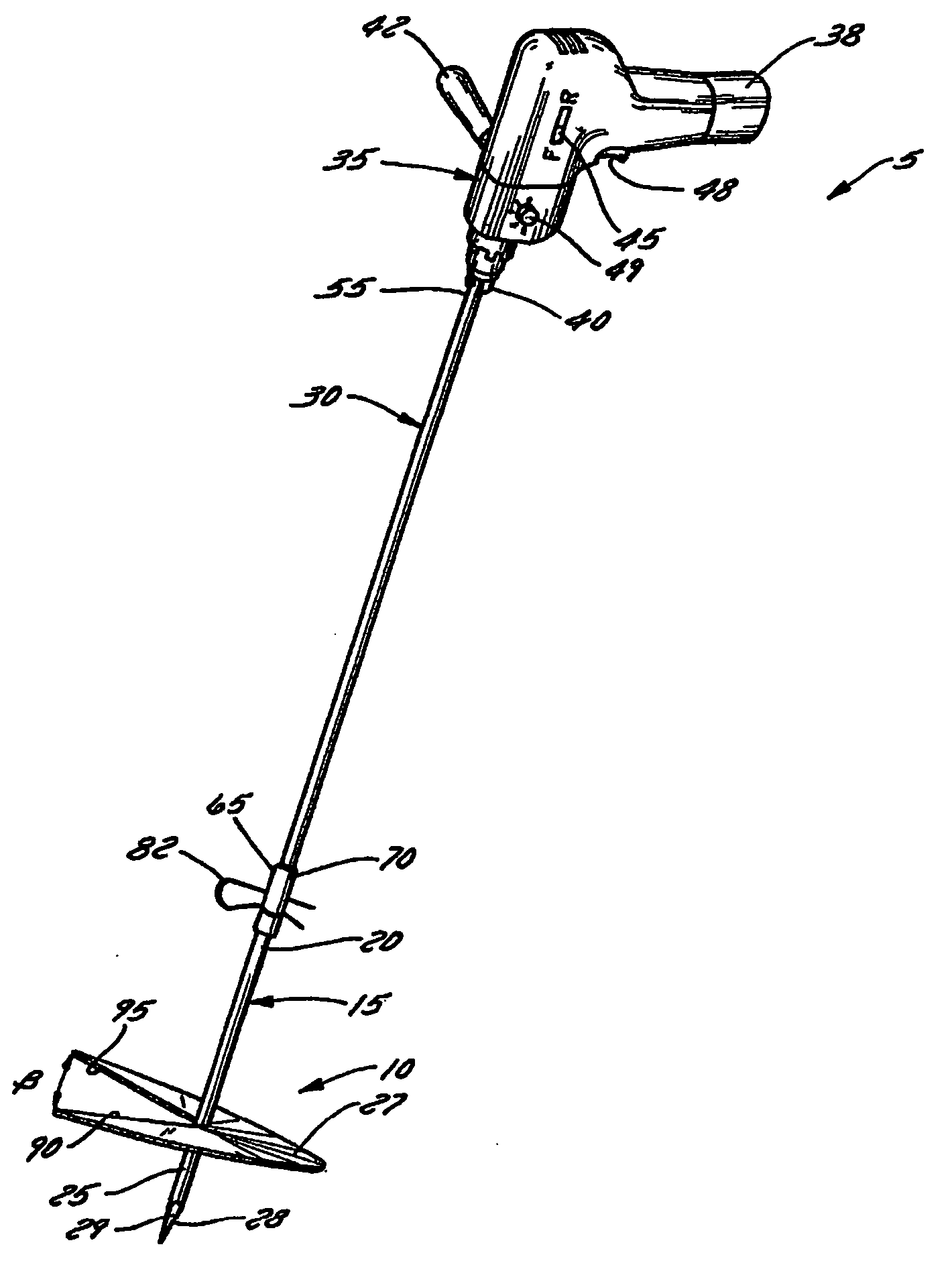
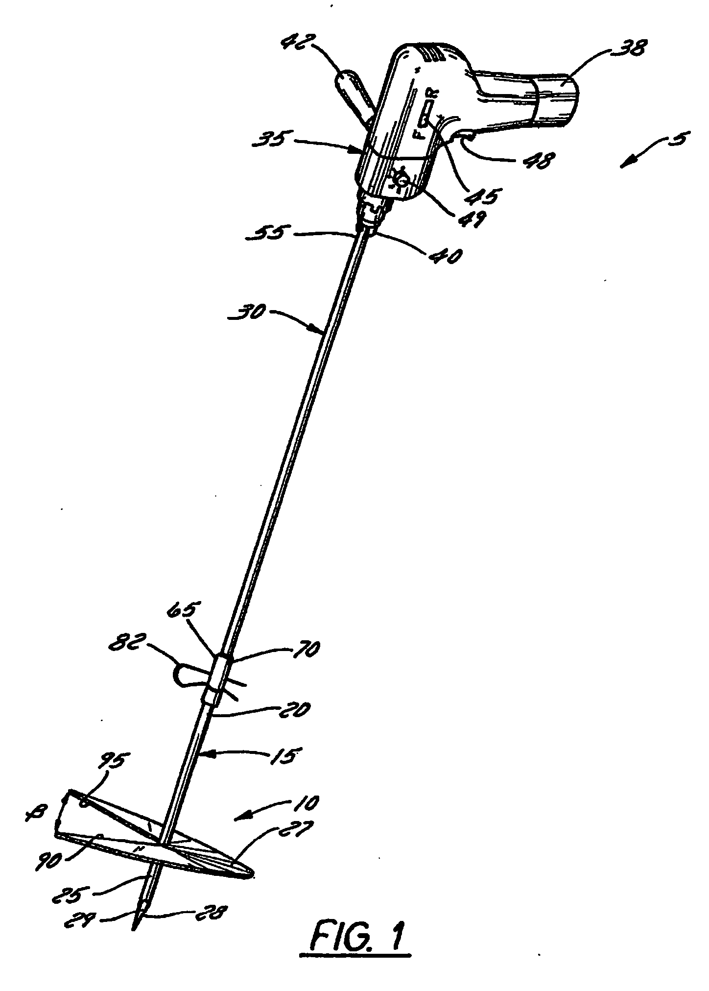
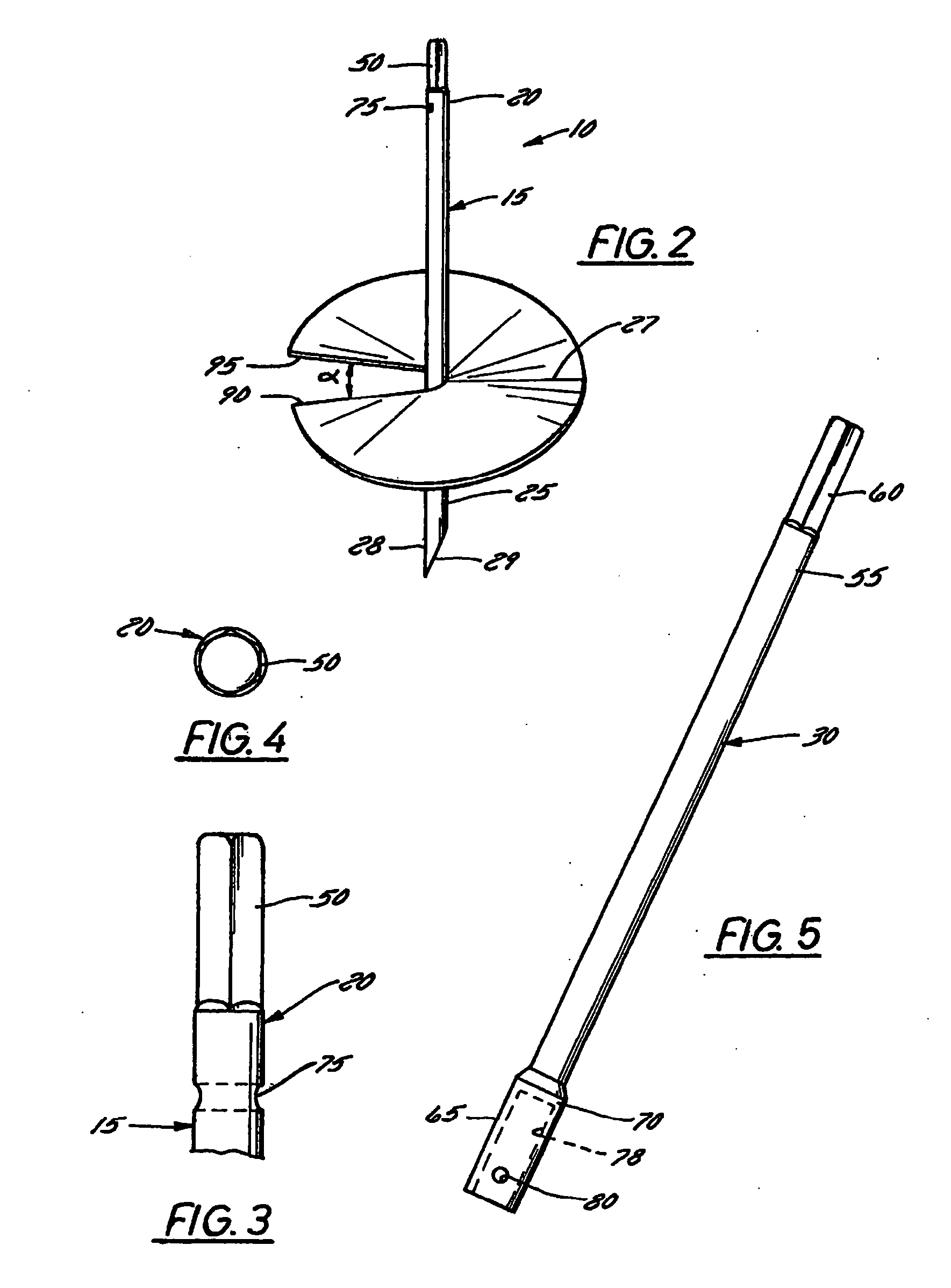
[0042] In its most basic form, the invention is an attachment to a device that provides power, such as a hand-held drill or a weed trimmer. The auger portion contains 1 to 4 discs which are rotated. They are connected to a shaft with a hex head which prevents it from slipping when power is applied. The attachment can be extended to about 26 inches long so the user can stand up while using it, and does not have to stoop over. A pin mechanism holds the first shaft to a second or extension shaft. The device is preferably zinc-coated steel so it is somewhat rust free. However, it may also be made of stainless steel. The power source can be a typical 12 volt or better electric drill, either portable, battery-operated type, or electrical or can be an electric or g...


PUM


Abstract

An auger to assist in ground burrowing or mixing paint or concrete, is used by attaching it to an electric or cordless power source. The major advantages over previous augers are: a hex head design prevents slipping in the drill chuck, an offset boring tip provides better digging, and a removable extension allows for the digging holes from a sitting or standing position possible without straining. The cutting edge of the auger's discs is sharpened and provided with a serrated edge for easier digging in hard soil. A single spring pin lock connects a first shaft to the extension shaft and multiple holes in the extension shaft allow for a multitude of auger heights.

Description

CROSS-REFERENCE TO RELATED APPLICATION [0001] This application is a continuation-in-part of now pending U.S. Ser. No. 10 / 251,731, filed Sep. 21, 2002, the entire contents of which are hereby expressly incorporated by reference into the present application.BACKGROUND OF THE INVENTION [0002] 1. Field of the Invention [0003] The present invention relates in general to the field of augers. More particularly, the present invention relates to an auger for use in boring and weeding. Specifically, one preferred embodiment of the present invention relates to an auger having an extension for use primarily around the home, lawn, or garden. [0004] 2. Discussion of the Related Art [0005] Historically, it was known in the prior art to use an auger device to make holes or to mix various liquids and solids. [0006] As is known to those skilled in the art, such auger attachments can be affixed to common hand tools with power sources such as an electric drill or weed eater device. However, a previousl...

Claims


Application Information

Patent Timeline
Patent Type & Authority Applications(United States)
IPC IPC(8): A01B33/06A01B1/06A01B13/00A01C7/02B01F7/00B01F13/00B01F15/00
CPCA01B1/065B01F13/002B01F7/00725B01F7/00416B01F27/1143B01F27/213B01F33/50115
Inventor MOTOSKO, THOMAS P.
Owner MOTOSKO THOMAS P
Why Eureka
Try Eureka