
Automatic exposure control for digital imaging

Inactive Publication Date: 2003-10-02
FREESCALE SEMICON INC
View PDF27 Cites 39 Cited by
  • Summary
  • Abstract
  • Description
  • Claims
  • Application Information

AI Technical Summary

Problems solved by technology

Conventional devices have not been able to achieve these aims.
Instead, they provide images whose exposure is not optimized, and those images often suffer from a low signal-to-noise ratio.
In particular, conventional techniques and algorithms have not been able to automatically process data such that digital image exposure is optimized, while achieving a high signal-to-noise ratio.
Rather, problems arise--objects appear too dark or light and / or an image exhibits noisy characteristics.
Although these techniques offer the user a great range of flexibility and control in determining the properties of an image, the more post-acquisition corrections that are applied to an image, the more the overall quality of an image may degrade.
For instance, heavy post-acquisition processing of an image may introduce unwanted digital artifacts.
Any problems or shortcomings enumerated in the foregoing are not intended to be exhaustive but rather are among many that tend to impair the effectiveness of previously known digital imaging and processing techniques.
Other noteworthy problems may also exist; however, those presented above should be sufficient to demonstrate that apparatus and methods appearing in the art have not been altogether satisfactory and that a need exists for the techniques disclosed herein.

Method used


Image

  • Automatic exposure control for digital imaging
  • Automatic exposure control for digital imaging

Examples


first embodiment

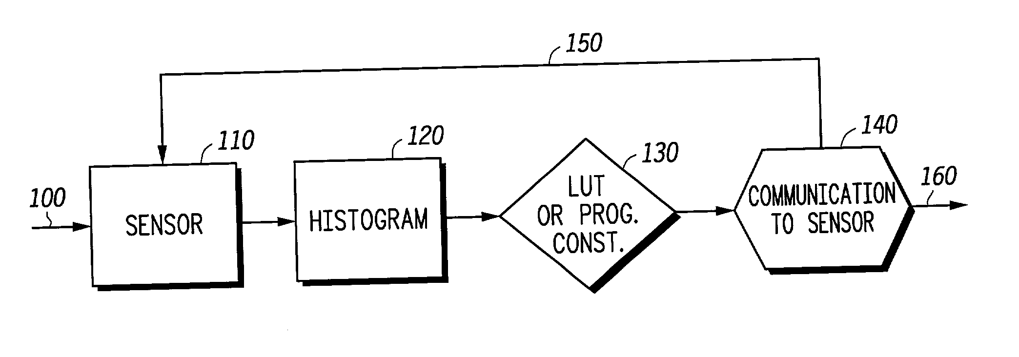
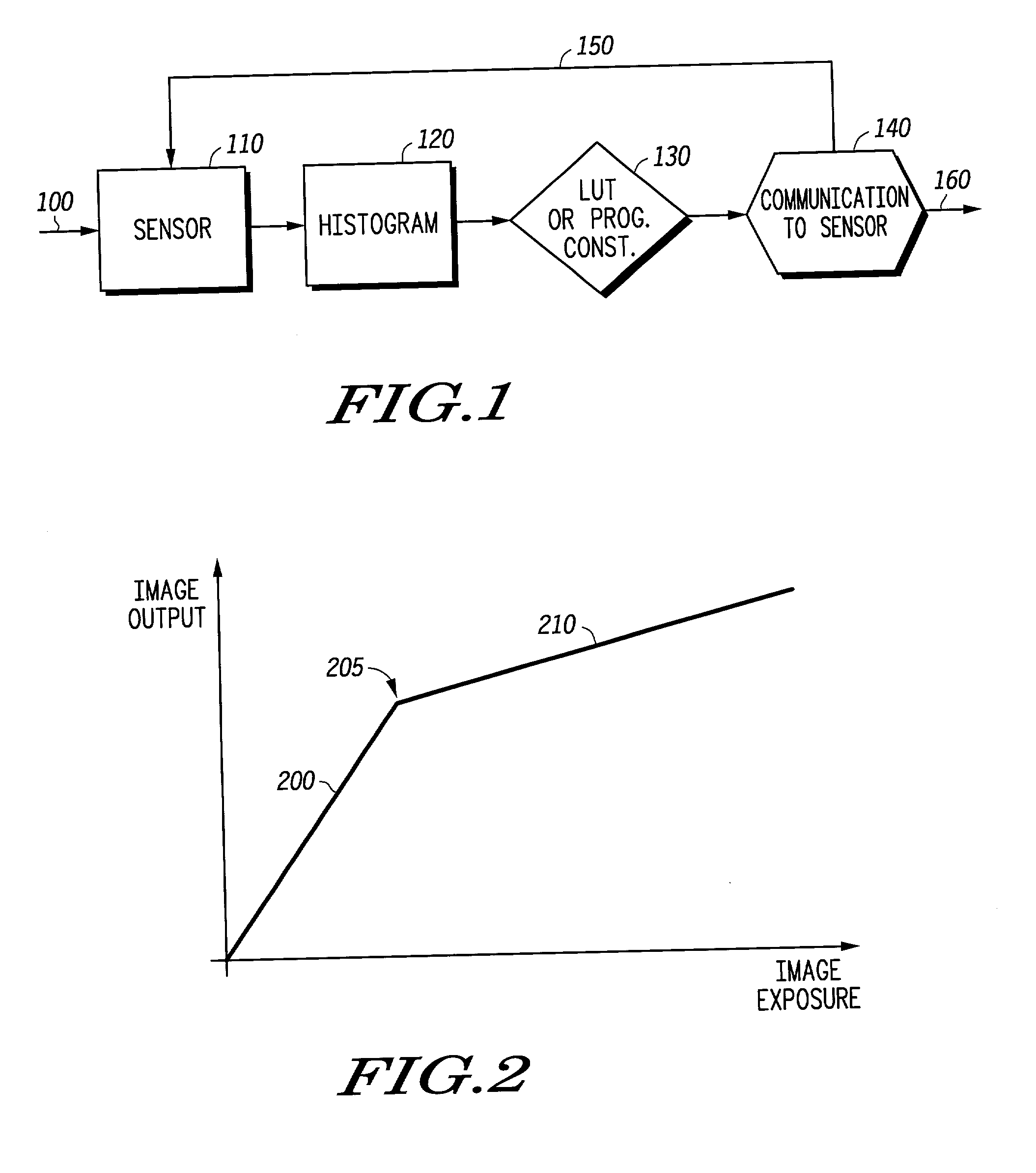
[0041] The difference between the median or mean provided by histogram block 120 and the target exposure level of LUT 130 gives both the direction and magnitude of the desired global (or, in a different embodiment, color-by-color) exposure increases or decreases required to achieve exposure compensation. There are at least two embodiments that may be used to achieve this increase or decrease. In a first embodiment, a fixed lookup table (e.g., LUT 130) may be used to determine the appropriate exposure compensation. For instance:

[0042] if Median-Target=<<<0, then a large exposure increase is applied to the sensor;

[0043] if Median-Target=<0, then a small exposure increase is applied to the sensor;

[0044] if Median-Target.apprxeq.0, then little if any exposure increase or decrease is applied to the sensor;

[0045] if Median-Target>>>0, then a large exposure decrease is applied to the sensor;

[0046] if Median-Target>0, then a small exposure decrease is applied to the sensor.

[0047] In differe...

second embodiment

[0051] In a second embodiment, an absolute exposure increase or decrease may be applied, based upon the percentage difference between the target and measured exposure levels. For instance:

Exposure.sub.new=Exposure.sub.current+(% difference)*Exposure.sub.current; or, rewritten

Exposure.sub.new=Exposure.sub.current*(1+(% difference)),

[0052] where (% difference) is the percentage difference between the Median (or mean) and Target values (a positive percentage representing that the Target is greater than the Median). Thus if the Target is 20% greater than the Median (or mean), then:

Exposure.sub.new=Exposure.sub.current*(1.20).

[0053] In other words, the new exposure is increased by 20%. LUT block 130 may perform this calculation to determine the appropriate exposure compensation to be relayed to the sensor block 110.

[0054] Turning again to FIG. 1, feedback block 140 is shown. In one embodiment, feedback block 140 outputs final image data for use and / or viewing via signal 160. It also feed...


PUM


Abstract

In exposure control of a digital image, a signal is obtained from an image sensor. One or more color channels are obtained from the signal. A mean value from one or more of the color channels is determined. A target exposure level is obtained. The difference between the mean value and the target exposure level is determined. An exposure correction is determined based upon the difference. The exposure correction is fed back to the image sensor, and one or more settings of the image sensor are adjusted corresponding to the exposure correction.

Description

[0001] 1. Field of the Invention[0002] The invention relates generally to the field of digital imaging. More particularly, the invention relates to performing automatic exposure control on a digital image.[0003] 2. Related Art[0004] As digital imaging becomes more prevalent, technology strives to achieve images and video with better resolution and color accuracy. One aim is to achieve images in which objects are exposed properly--i.e., not too bright or too dark, moving the digital information histogram to an optimal point within the bounds of the maximum and minimum output signal levels of the system. Another related aim is to achieve images that are properly exposed and which exhibit a high signal-to-noise ratio--i.e., properly-exposed images that do not show many noise artifacts. Conventional devices have not been able to achieve these aims. Instead, they provide images whose exposure is not optimized, and those images often suffer from a low signal-to-noise ratio.[0005] Presentl...

Claims


Application Information

Patent Timeline
IPC IPC(8): H04N5/235
CPCH04N5/2351H04N5/235H04N23/71H04N23/70
Inventor SKOW, MICHAEL
Owner FREESCALE SEMICON INC
Learn More