Method for controlling auto-exposure

a technology of auto-exposure and control method, which is applied in the field of auto-exposure control method, can solve the problems of not being able to apply the conventional auto-exposure algorithm to the camera module, and taking a lot of time to determine the proper exposure value, so as to achieve optimal exposure and reduce the amount of hardware calculation.

Inactive Publication Date: 2010-06-03
SAMSUNG ELECTRO MECHANICS CO LTD
View PDF7 Cites 39 Cited by
  • Summary
  • Abstract
  • Description
  • Claims
  • Application Information

AI Technical Summary

Benefits of technology

[0007]An aspect of the present invention provides a fast and stable auto-exposure control method of a digital image capturing device such as a digital camera, a compact camera module, and the like.
[0017]In addition, the table for determining for an exposure time and an analog gain of the image sensor is created in consideration of a flicker, to thereby prevent generation of a flickering phenomenon in the auto-exposure controlling process.
[0018]Also, in the process of calculating the average luminance of an image frame obtained by the image sensor, the amount of calculation of hardware is reduced through image cropping, sectioning, weight value applying, region selecting, and the like, and an important portion of the image can be optimally exposed.

Problems solved by technology

Thus, it is not possible to apply the conventional auto-exposure algorithms to a camera module installed in the mobile communication terminals or in vehicles that do not have a dedicated processor of high performance for image processing due to a cost or size-related problem, and if ever, much time would be taken to determine a proper exposure value because of a huge amount of calculation and the like.

Method used


Image

  • Method for controlling auto-exposure
  • Method for controlling auto-exposure
  • Method for controlling auto-exposure

Examples


Embodiment Construction

[0027]Exemplary embodiments of the present invention will now be described in detail with reference to the accompanying drawings. The invention may however be embodied in many different forms and should not be construed as limited to the embodiments set forth herein. Rather, these embodiments are provided so that this disclosure will be thorough and complete, and will fully convey the scope of the invention to those skilled in the art. In the drawings, the shapes and dimensions may be exaggerated for clarity, and the same reference numerals will be used throughout to designate the same or like components.

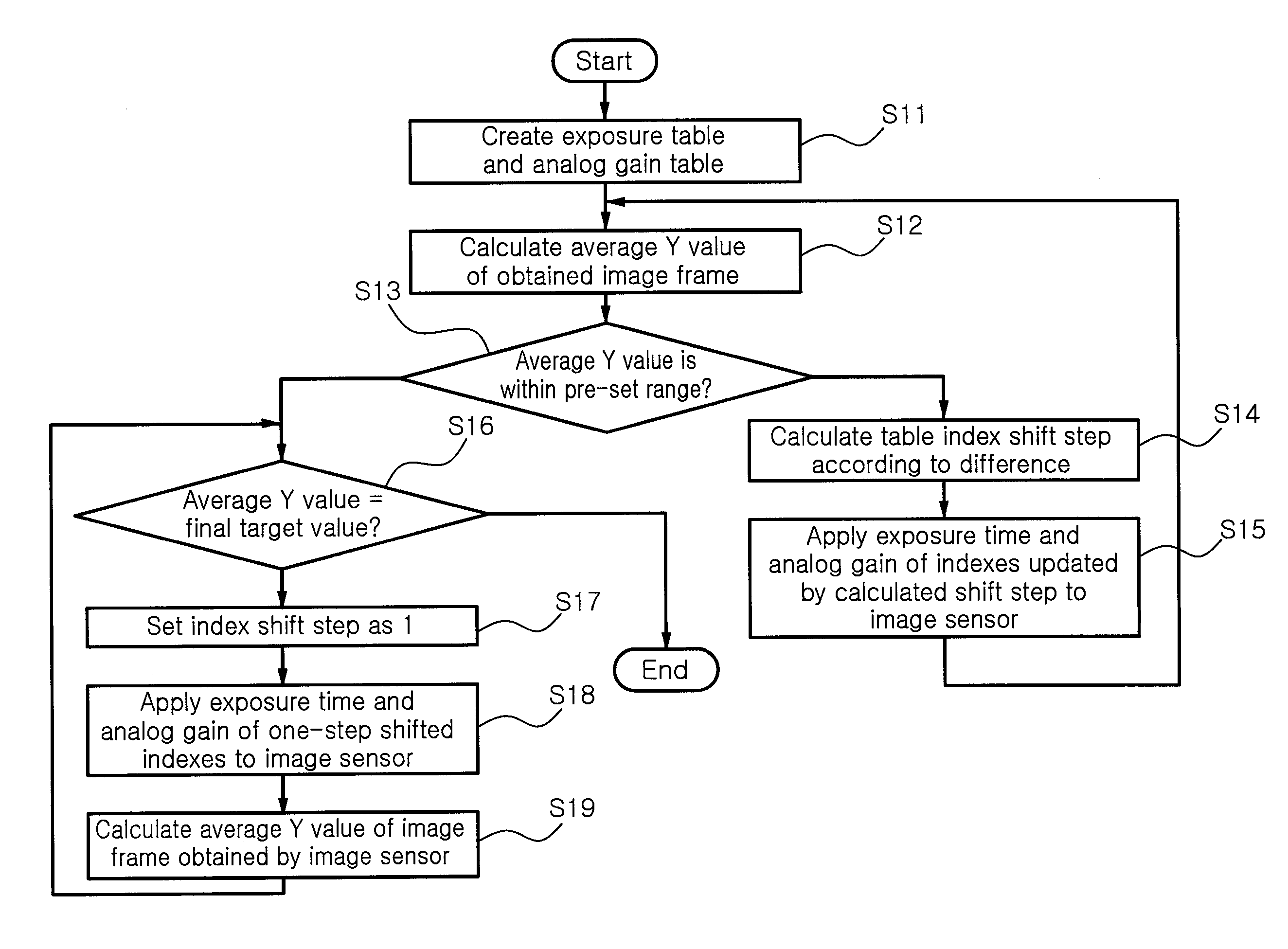
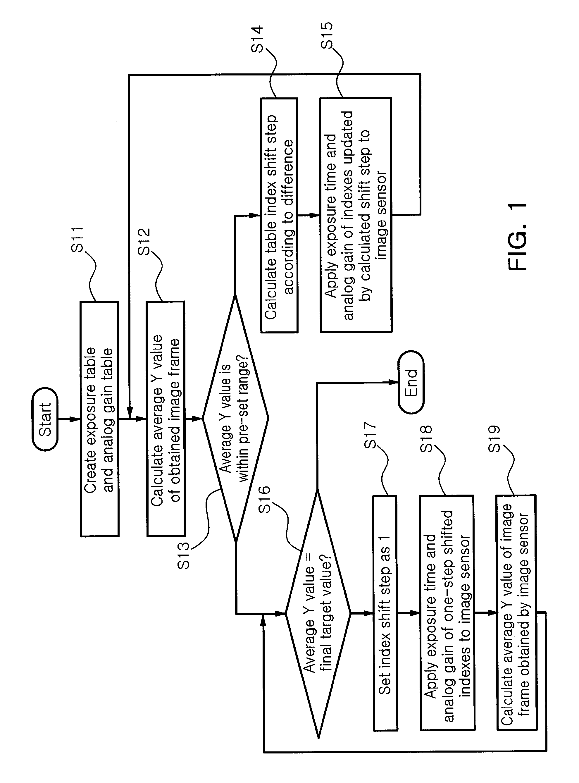
[0028]FIG. 1 is a flow chart illustrating an auto-exposure control method according to an embodiment of the present invention.

[0029]As shown in FIG. 1, the auto-exposure control method according to an embodiment of the present invention includes a step (S11) of creating an exposure table and analog gain table, a step (S12) of calculating an average luminance value (Y value) of an im...


PUM


Abstract

An auto-exposure control method includes: creating an exposure table and an analog gain table including an exposure time and an analog gain of an image sensor set according to an index, respectively; calculating an average luminance value of an image frame obtained by the image sensor; checking whether or not the average luminance value is within a pre-set range including a prescribed final target value; if the average luminance value is not within the pre-set range, determining a shift step from indexes which have been applied to a current image frame according to the difference between the average luminance value and the final target value in order to determine indexes of the exposure table and the analog gain table to be applied to a next image frame; and repeatedly performing of reading an exposure time and an analog gain corresponding to the indexes shifted by the shift step determined from the indexes applied to the current image frame, from the exposure table and the analog gain table, applying the same to the image sensor, obtaining a next image frame, and calculating an average luminance value.

Description

CROSS-REFERENCE TO RELATED APPLICATIONS[0001]This application claims the priority of Korean Patent Application No. 2008-0120545 filed on Dec. 1, 2008, in the Korean Intellectual Property Office, the disclosure of which is incorporated herein by reference.BACKGROUND OF THE INVENTION[0002]1. Field of the Invention[0003]The present invention relates to an auto-exposure control method and, more particularly, to a fast and stable auto-exposure control method of a digital image capturing device using an image sensor such as a digital camera, a compact camera module, and the like.[0004]2. Description of the Related Art[0005]Recently, a compact camera module employing an image sensor such as a CCD or a CMOS is installed in a mobile communication terminal to provide a camera function and also actively applied for vehicles to monitor front and rear blind spots.[0006]Thus, algorithms for applying various camera functions such as auto-focusing (AF), auto-white balance (AWB), auto-exposure (AE),...

Claims


Application Information

Patent Timeline
Patent Type & Authority Applications(United States)
IPC IPC(8): H04N5/235
CPCH04N5/2351H04N5/243H04N5/2357H04N5/2352H04N23/72H04N23/745H04N23/71H04N23/76H04N23/73H04N23/741
Inventor KIM, GYU WONKIM, HAK SUNCHOI, WON TAEMIN, KYOUNG JOONGHA, JOO YOUNG
Owner SAMSUNG ELECTRO MECHANICS CO LTD
Why Eureka
Try Eureka