Method and apparatus for creating software objects

a software object and method technology, applied in the field of computer software, can solve the problems of chance of making an error, the explicit nature of these tools has not changed, and the number of limitations in the approach to creating source objects

Inactive Publication Date: 2003-10-23
IBM CORP
View PDF3 Cites 128 Cited by
  • Summary
  • Abstract
  • Description
  • Claims
  • Application Information

AI Technical Summary

Benefits of technology

[0030] All of the approaches described in this section seek to improve user productivity in the creation of source objects by providing some form of pre-processing, or post-processing of source objects. The premise behind all of these approaches is that 1) users must still create some representation of a source object through an explicit editing means, and that 2) all processing of source objects takes place either before or after the explicit editing process performed by the user.
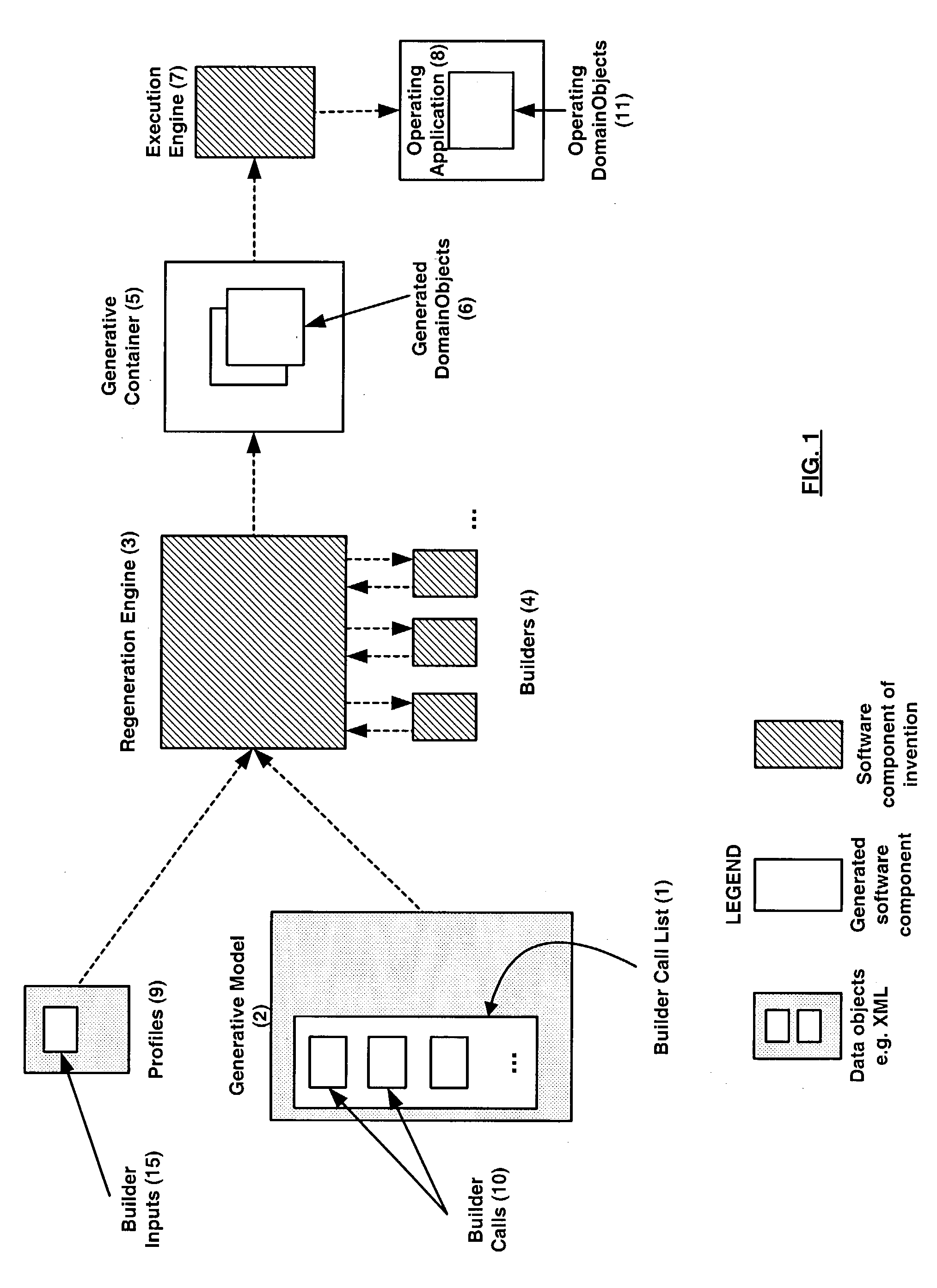
[0032] The present invention offers an approach for capturing process definitions for creating software objects, as supposed to prior art approaches that only allow for capturing a representation of an object explicitly. Prior art explicit editing approaches provide tools for users to create objects through explicit editing means. With such means, users can create and modify software objects by directly manipulating entities in the software objects, and by saving the resulting objects. The present invention provides a different approach, whereby a user creates an object called a Generative Model, which contains a process definition for creating an object by way of executing a set of software generators called Builders. Furthermore, the process definition allows the user to capture the process of object creation in a manner that can be re-executed to generate a wide variety of software objects.
[0041] In one embodiment of the present invention, the regeneration function performs the task of creating one or more System Logic Objects from scratch, using a definition of the construction process to be performed. The Generative Model defines this construction process, and the set of input parameters serve to configure the construction process. By changing the input parameters, and utilizing a single Generative Model, the regeneration function is able to instantiate different configurations of the construction process. Each potentially unique configuration of the construction process is able to produce a different generated set of output objects.

Problems solved by technology

Furthermore, even with the emergence of powerful graphical "drag and drop" tools, and fancy wizards and macros, the explicit nature of these tools has not changed.
There are a number of limitations in approaches to creating source objects using "explicit" authoring tools that employ direct manipulation of the entities.
1) The process of creating the objects is not captured and saved in any form of a computer-based re-executable format. These tools perform a set of user-driven explicit editing operations (via direct create, delete, and modify of object entities), and they capture and store only the final representation of the object. As such, the author must manually repeat various steps of the creation and modification process in order to produce a different variation of the object. For example, using an explicit editing tool, if a user added entity A to an object, and then modified a portion of A, to produce A', and then added B, then the system would save A'B. The editing process of going from A to A' to A'B would never be captured. Only the result would be captured. As such, if the user wanted to produce a variation of the object in the form of AB, s / he would have to repeat the steps of adding an A and then going directly to the step of adding a B.
2) When an author makes a change to an object, there is a chance for making an error, since the author is performing the editing process manually, and directly upon the object. For example, if a user deletes and recreates an entity A that had been modified to A' in the original object, there is a chance that the user will make a mistake and not perform the same explicit operation(s) that led to the creation of A.
3) In order to create an object that satisfies a set of conflicting requirements, an author must create multiple instances of the object, often with a large amount of duplication among the object instances. For example, a user would have to produce two objects, AB, and A'B in order to have two different representations of the object.
However, none of these approaches eliminate the need for a user to create an explicit representation of a source object, no matter how high-level or small in granularity it may be.

Method used


Image

  • Method and apparatus for creating software objects
  • Method and apparatus for creating software objects
  • Method and apparatus for creating software objects

Examples


case 1

[0185] Case 1

[0186] if (a>0) {action1( );

[0187] }

[0188] Following is an example of two behaviors, where the second behavior has a condition, which is the negative of the condition of the first behavior. This is the familiar if-then-else behavior.

case 2

[0189] Case 2

[0190] if (a>0) {action1( );

[0191] } else {action0( );

[0192] }

[0193] FIG. 13 shows a graphical representation of Case 2 expressed in the rule format. Base Rule (58) (rule1) has a condition (57) and two actions (59) and (60). Again, a Base Rule can have any patterns representing its pre and test conditions, and any two actions. In addition, a Base Rule may also have no action or actions associated with the then and else cases.

[0194] The Base Rule Builder also has optional inputs for associating the behavior with a "from" state, and a pair of "to" states associated with the "then" and "else" cases. By specifying "from" and "to" states via the Builder Input parameters, the user supplies the Builder with information that enables it to construct additional patterns in the base rule conditions that ensure that the computing system possesses the from state in order to activate the behavior and cause either the "then" or "else" actions to execute. By specifying a "To" state for...

case 3

[0195] Case 3 shows one of many ways in which a Base Rule can have additional patterns and actions that cause it to exhibit additional behaviors. Here, the Base Rule is able to activate if the phase is at a RUN state. If it is, then the conditions are checked, and the then or else actions may execute. In addition, the rule causes the phase to change to RUN, or RESET. FIG. 14 shows the corresponding Base Rule 62 (rule1), which has conditions (63) and (64). Note that condition (63) is a phase check. Once the conditions are checked, then either action (65) and (67) is executed, along with the appropriate phase setting mechanism (66) or (68).

[0196] The Base Rule Builder has an optional input called: Fire Once Before Reset, which can be set to true or false. This Builder Input causes the Builder to determine whether or not to construct additional conditions and actions in the rule that govern the rule's ability to fire multiple times before the state of the entire system logic object has...


PUM


Abstract

The invention provides a method and apparatus for the dynamic generation and regeneration of software objects that can have logic that specifies structure, functionality and behavior in a computing system. One embodiment is the regeneration function that produces related, but different instances of software objects, including System Logic Objects. The regeneration function comprises ordered sequences of tasks, whose definition, and parameterization are obtained from a Generative Model, and which are performed by software objects called Builders. Each Builder accepts a set of input parameters and a reference to a container that contains zero or more generated software objects, including System Logic Objects. The regeneration function directs each Builder to work on the contents of the container, add, modify, and delete objects, and return the container with updated contents. The behavior of the regeneration function can be altered by disabling selected Builders, and by changing the inputs to the Builders.

Description

[0001] This application claims the benefit of priority from U.S. Provisional Application titled "Method and Apparatus for Creating System Logic," Serial No. 60 / 334,207, filed Nov. 28, 2001.[0002] 1. Field of the Invention[0003] The present invention relates in general to computer software, and in particular to a software system that dynamically creates objects used by computing systems. More specifically, but without restriction to the particular embodiments hereinafter described in accordance with the best mode of practice, this invention relates to a method and system for dynamically creating source objects that represent embodiments of logic used in computing systems. These embodiments of logic are referred to as System Logic Objects.[0004] 2. Background Art[0005] In the past, people have provided tools that assist programmers in the creation of the source objects that define the structure, functionality, and behavior of programs on computing systems. Examples of source objects i...

Claims


Application Information

Patent Timeline
Patent Type & Authority Applications(United States)
IPC IPC(8): G06F9/44G06FG06F9/455G06N5/02
CPCG06N5/02G06F8/24
Inventor ROBERTS, ANDREW F.BOOTH, JONATHANZAGIEBOYLO, STEPHEN
Owner IBM CORP
Why Eureka
Try Eureka